Steam generating method and apparatus for simulation test chambers

a technology of steam generator and test chamber, which is applied in the direction of steam generation using hot heat carriers, lighting and heating apparatus, immersion heating arrangements, etc., can solve the problems of generators located in difficult to access areas, valves and other moving parts not generating the proper amount of steam, etc., and achieves the effect of simple cleaning

Inactive Publication Date: 2005-04-07
TPS
View PDF34 Cites 32 Cited by
  • Summary
  • Abstract
  • Description
  • Claims
  • Application Information

AI Technical Summary

Benefits of technology

[0007] The foregoing needs are met, to a great extent, by the present invention, wherein in one aspect an apparatus is provided that in some embodiments provides a steam generator of a simplified design that locates the valves and other moving parts associated with a steam generator in easy to access location and that allows for simplified cleaning and flushing the system to remove sediment and other types of buildup.

Problems solved by technology

Not supplying enough water to the heating element can cause a multitude of problems, including not generating the proper amount of steam and also other problems associated with overheating the heating element.
Other problems associated with current steam generators are that valves and other moving parts which may contribute to the control and / or operation of the steam generator may be located in hard to access areas.
Locating moving parts that need servicing in hard to access areas may increase the difficulty of servicing and / or manufacturing the steam generator.
Other problems with some known steam generators are that they have complex designs which result in high manufacturing costs.
Another problem associated with some steam generators is that they are hard to clean and service.
Additionally, they may not easily allow water to be drained from them in order to flush sediment and other types of build-up that occur within the steam generator.

Method used


Image

  • Steam generating method and apparatus for simulation test chambers
  • Steam generating method and apparatus for simulation test chambers
  • Steam generating method and apparatus for simulation test chambers

Examples


Embodiment Construction

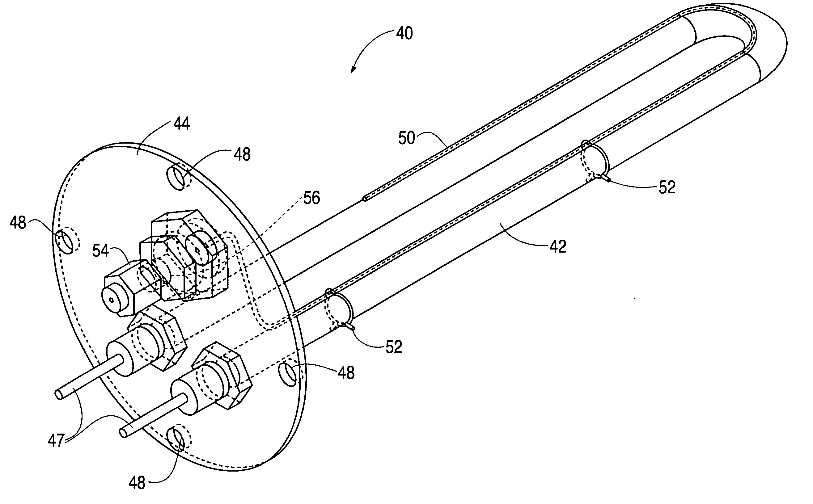
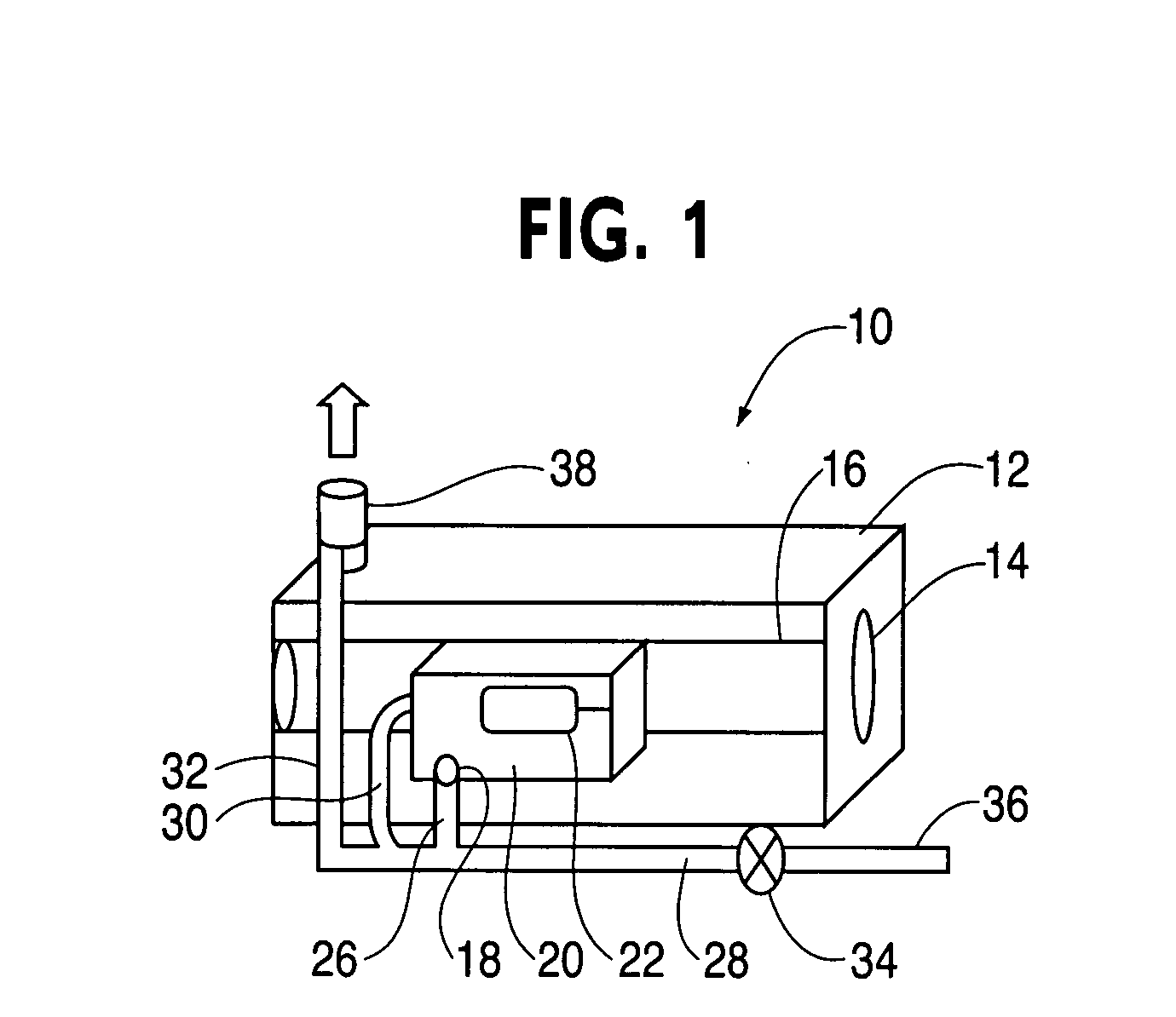
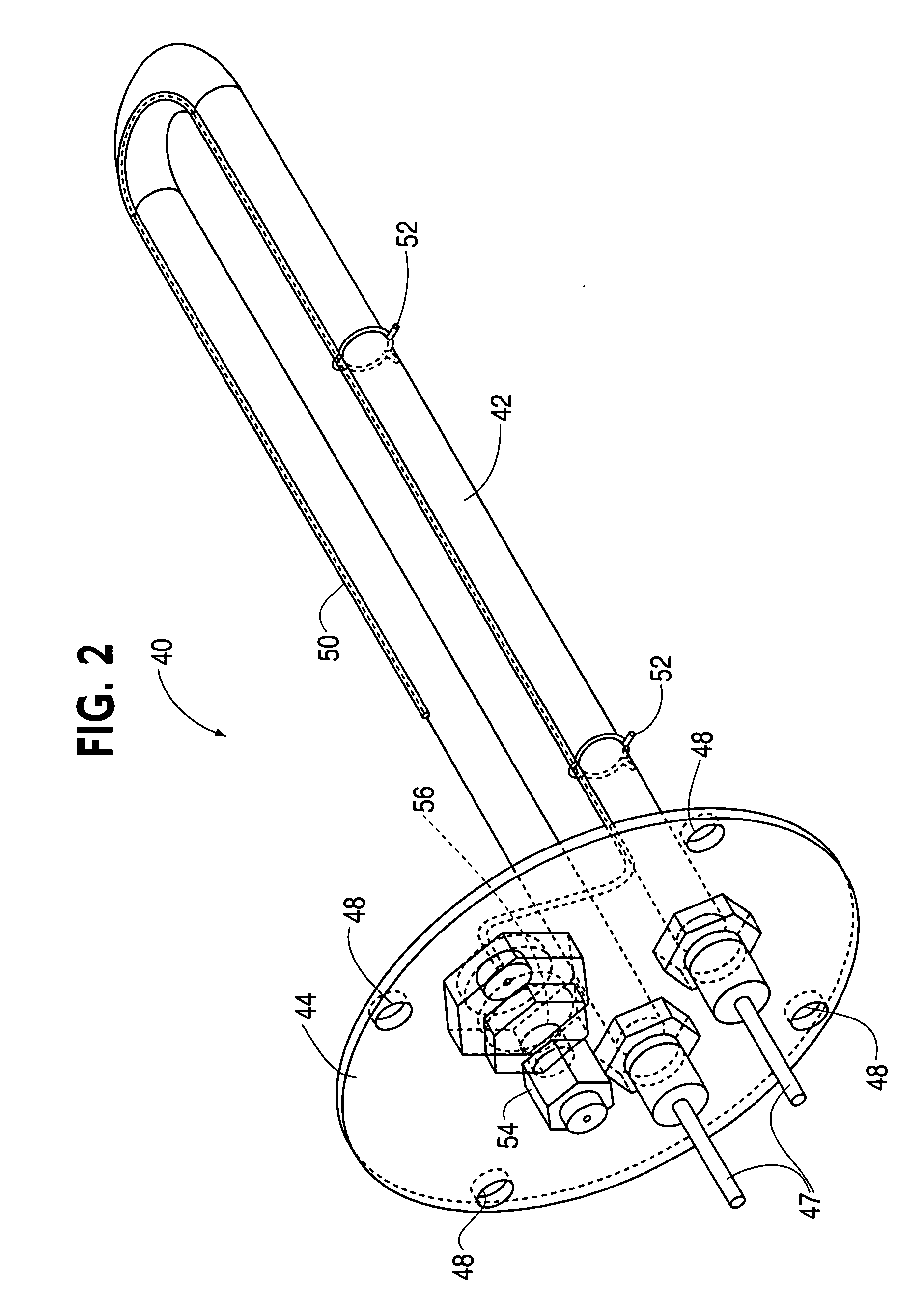
[0023] The invention will now be described with reference to the drawing figures in which like reference numerals refer to like parts throughout. An embodiment in accordance with the present invention provides a steam generator having a tubular evaporator that is easily removed from the steam generator. Water is inlet to the evaporator where a heating element heats the water to steam. The steam is then vented out of the evaporator and steam generator. The valves for controlling water flow and other moving parts associated with the steam generator are located in a side box that is easily accessed. The easy access features provide, among other things, ease of maintenance.

[0024] It is understood that the term water as used herein is not limited to pure H2O only, but includes water and impurities often found in tap water and other water sources. The term water includes water having any trace impurities.

[0025] Turning now to the drawings, an embodiment of the present inventive apparatu...


PUM


Abstract

A method and apparatus for providing steam for a test chamber is provided. The apparatus includes a heating element contained within a vessel which is fluid communication with an exterior reservoir wherein the heating element provides heat to generate steam from the water entering the vessel from the reservoir. The method for generating steam includes providing a chamber configured to contain a fluid insetting water into the chamber from a reservoir external from the chamber, controlling an amount of water inlet into the reservoir substantially equalizing the water level in the reservoir with the water level in the chamber. The method also includes heating the water in the chamber to turn at least some of the water into steam and venting at least some of the steam out of the chamber.

Description

FIELD OF THE INVENTION [0001] The present invention relates generally to steam generators. More particularly, the present invention relates to steam generators for use in test ovens and other industrial test chambers. BACKGROUND OF THE INVENTION [0002] Simulation test chambers are chambers designed to replicate certain environmental conditions. Objects are placed in the chambers and are evaluated to see how well the object performs under certain conditions. A test chamber may be refrigerated to cold temperatures or may be heated to certain high temperatures. Along with the temperature, humidity is also controlled to see how an object performs under various humid conditions. [0003] In order to provide humidity for a test chamber, a steam generator is often used. In some steam generators, steam is generated by applying water to a heating element. The heating element boils the water and generates steam. Not supplying enough water to the heating element can cause a multitude of problems...

Claims


Application Information

Patent Timeline
Patent Type & Authority Applications(United States)
IPC IPC(8): F22B1/28
CPCF22B1/284
Inventor POWELL, RICHARD M.HESS, BRUCE W.
Owner TPS
Why Eureka
Try Eureka