Steering wheel mounted scroll wheel and method

a technology of steering wheel and scroll wheel, which is applied in the direction of dashboard fitting arrangement, electric devices, transportation and packaging, etc., can solve the problems of affecting the driving experience of drivers, and the driver is less able to react quickly to the conditions on the road

Inactive Publication Date: 2005-04-07
GENERAL MOTORS COMPANY
View PDF12 Cites 43 Cited by
  • Summary
  • Abstract
  • Description
  • Claims
  • Application Information

AI Technical Summary

Benefits of technology

[0005] An apparatus is provided for an intuitive and non-distracting way for a driver of a motor vehicle to access and adjust vehicle system settings. The apparatus comprises a plurality of rotary scroll wheels and a plurality of switches, each of the plurality of switches coupled to and actuable by one of the rotary scroll wheels, and each of the plurality of rotary scroll wheels mounted on a steering wheel rim of the motor vehicle. Preferably, one of the rotary scroll wheels is mounted in an upper right hand quadrant of the steering wheel rim and one is mounted in an upper left hand quadrant. The apparatus further includes a control unit electrically coupled to each of the plurality of switches and configured to cause a motor vehicle function to react to a signal received from at least one of the plurality of switches.

Problems solved by technology

The buttons that comprise most current steering wheel controls often provide a non-intuitive interface with vehicle systems because they require that the driver toggle multiple times to reach a desired setting, thereby distracting the driver's attention from the road.
Also, the location of the controls, most commonly on the steering wheel web, hub, and stalk, requires that a driver move his or her hands from the normal driving position in order to use the buttons, making the driver less able to quickly react to conditions on the road (swerving to miss some road debris, for example) if such conditions should occur while the driver is adjusting one of the controls.

Method used


Image

  • Steering wheel mounted scroll wheel and method
  • Steering wheel mounted scroll wheel and method
  • Steering wheel mounted scroll wheel and method

Examples


Embodiment Construction

[0012] The following detailed description is merely exemplary in nature and is not intended to limit the invention or the application and uses of the invention. Furthermore, there is no intention to be bound by any expressed or implied theory presented in the preceding technical field, background, brief summary or the following detailed description.

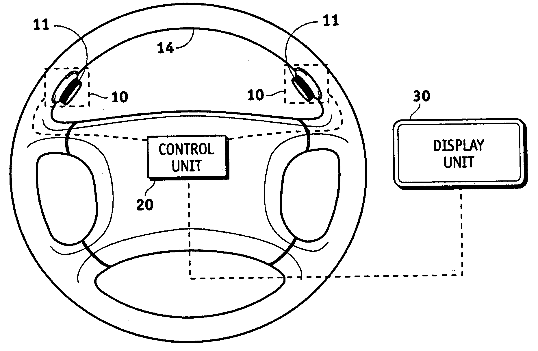
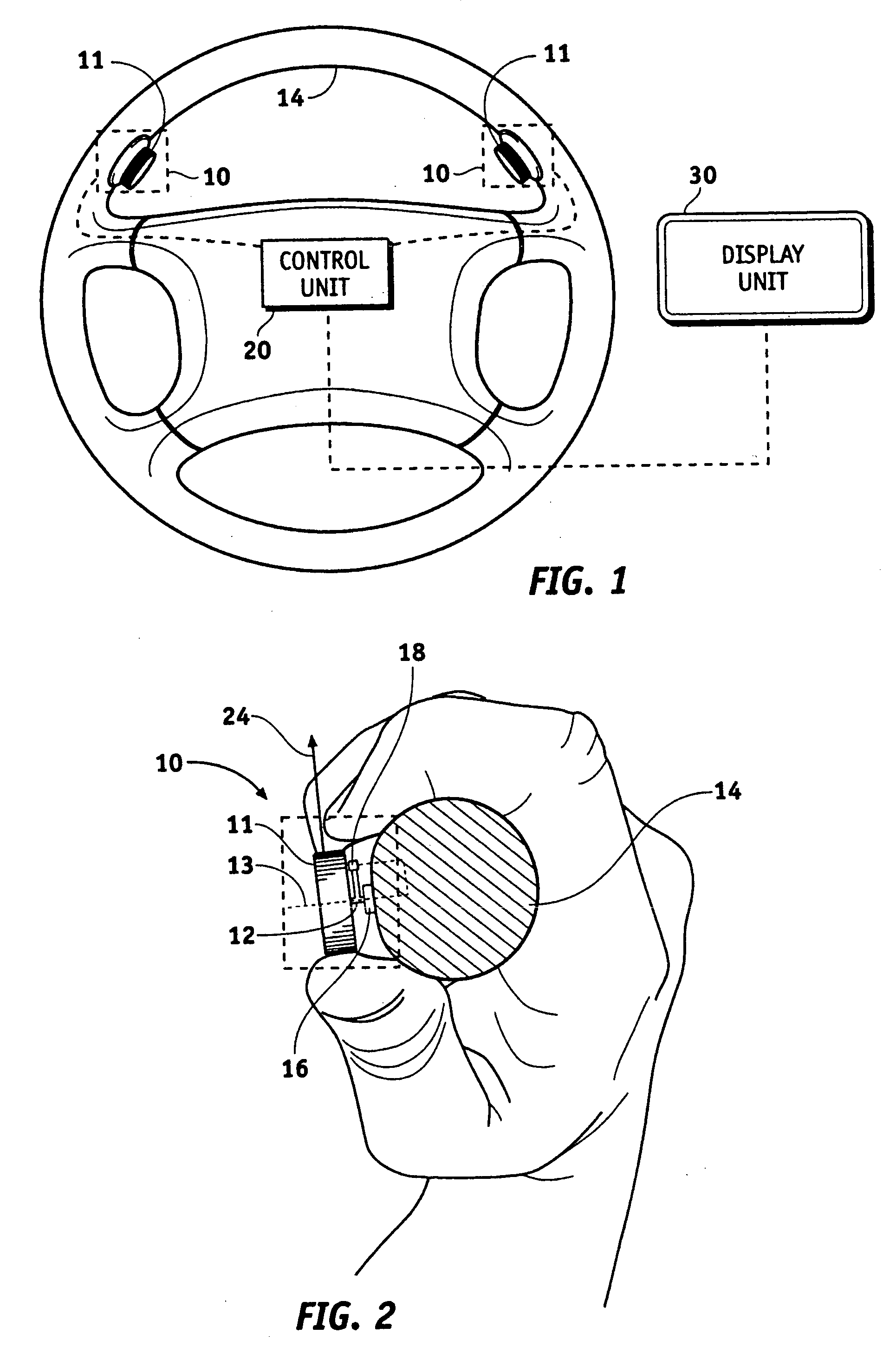
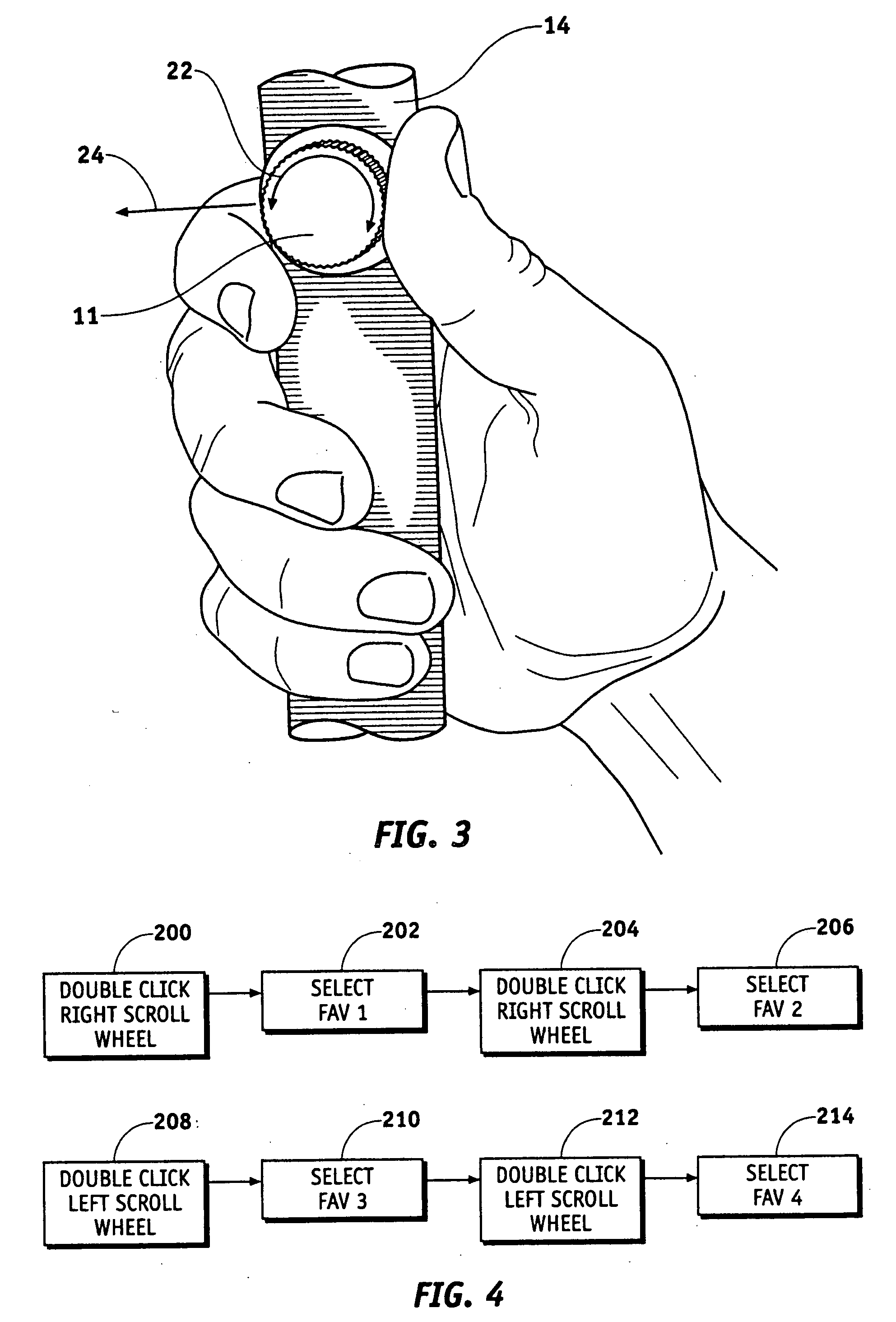
[0013] In accordance with the invention, a steering wheel mounted control system is provided that includes one or more steering wheel mounted scroll wheels. The steering wheel mounted scroll wheels provide an intuitive and non-distracting means through which the driver of a motor vehicle can access and adjust vehicle system settings, such as vehicle speed, passenger cabin temperature, and the like. In accordance with an embodiment of the invention, the scroll wheels are positioned on a steering wheel at locations proximate the locations where a driver normally grips the steering wheel such that a driver can access them conveniently witho...


PUM


Abstract

Methods and apparatus are provided for an intuitive and non-distracting way for a driver of a motor vehicle to access and adjust vehicle system settings. The apparatus comprises a plurality of rotary scroll wheels and a plurality of switches, each of the plurality of switches coupled to and actuable by one of the scroll wheels, and each of the plurality of rotary scroll wheels mounted on a steering wheel rim of the motor vehicle. Preferably, one of the scroll wheels is mounted in an upper right hand quadrant of the steering wheel rim and one is mounted in an upper left hand quadrant. The apparatus further includes a control unit electrically coupled to each of the plurality of switches and configured to cause a motor vehicle function to react to a signal received from at least one of the plurality of switches.

Description

TECHNICAL FIELD [0001] The present invention generally relates to motor vehicle control systems, and more particularly relates to steering wheel mounted scroll wheel control systems and to methods for their operation. BACKGROUND [0002] Many modern motor vehicles employ steering wheel-mounted controls that are intended to allow the driver of the motor vehicle to operate certain motor vehicle functions without completely removing his or her hands from the steering wheel and without requiring the driver to divert much of his or her attention from the road. These controls, usually buttons located on the steering wheel web, stalk, or hub, may control a variety of different vehicle systems, including the cruise control system, the radio, and the heating / ventilation air conditioning (HVAC) system. Thus, a vehicle equipped with steering wheel controls allows a driver to change a radio station, alter the passenger cabin temperature, adjust the speed of the vehicle, or modify other vehicle sy...

Claims


Application Information

Patent Timeline
Patent Type & Authority Applications(United States)
IPC IPC(8): B60K37/06B60L3/00
CPCB60K2350/928B60K37/06B60K2370/113B60K2370/117B60K2370/782
Inventor POPILEK, MARK E.
Owner GENERAL MOTORS COMPANY
Why Eureka
Try Eureka