Method of applying an encapsulant material to an ink jet printhead

a technology of encapsulant material and ink jet printhead, which is applied in the direction of printing, etc., can solve the problems of inability to apply a length of sealing tape to the printhead, and inability to meet the requirements of printing

Inactive Publication Date: 2005-04-07
FUNAI ELECTRIC CO LTD
View PDF42 Cites 26 Cited by
  • Summary
  • Abstract
  • Description
  • Claims
  • Application Information

AI Technical Summary

Benefits of technology

[0009] A method for protecting electrical traces on a flexible circuit and connections between the traces and a heater chip/nozzle plate assembly for an ink jet printer is also provided. The method includes providing a stencil having one or more apertures, applying an encapsulant material through the apertures onto the electrical traces and the connections between the traces and the heater chip/nozzle plate assembly. The method may utilize a stencil made of polyimide, fluoropolymer coated polyimide, stainless steel or combinations thereof. In accordance with certain aspects of the invention, the method includes aligning the stencil such that the apertures align with the electrical traces and the connections between the traces and the heater chip/nozzle plate assembly, depositing the encapsulant material on the stencil and extrudi...

Problems solved by technology

The final height of the barrier layer relative to the nozzle plate typically is undesirably high.
The excessive height of the barrier layer is further problematic as it makes it more difficult to apply a length of sealing tape to the printhead so as to seal the printhead orifices from ink leakage until the print cartridge is installed for...

Method used


Image

  • Method of applying an encapsulant material to an ink jet printhead
  • Method of applying an encapsulant material to an ink jet printhead
  • Method of applying an encapsulant material to an ink jet printhead

Examples


Embodiment Construction

[0016] All documents cited are, in relevant part, incorporated herein by reference; the citation of any document is not to be construed as an admission that it is prior art with respect to the present invention.

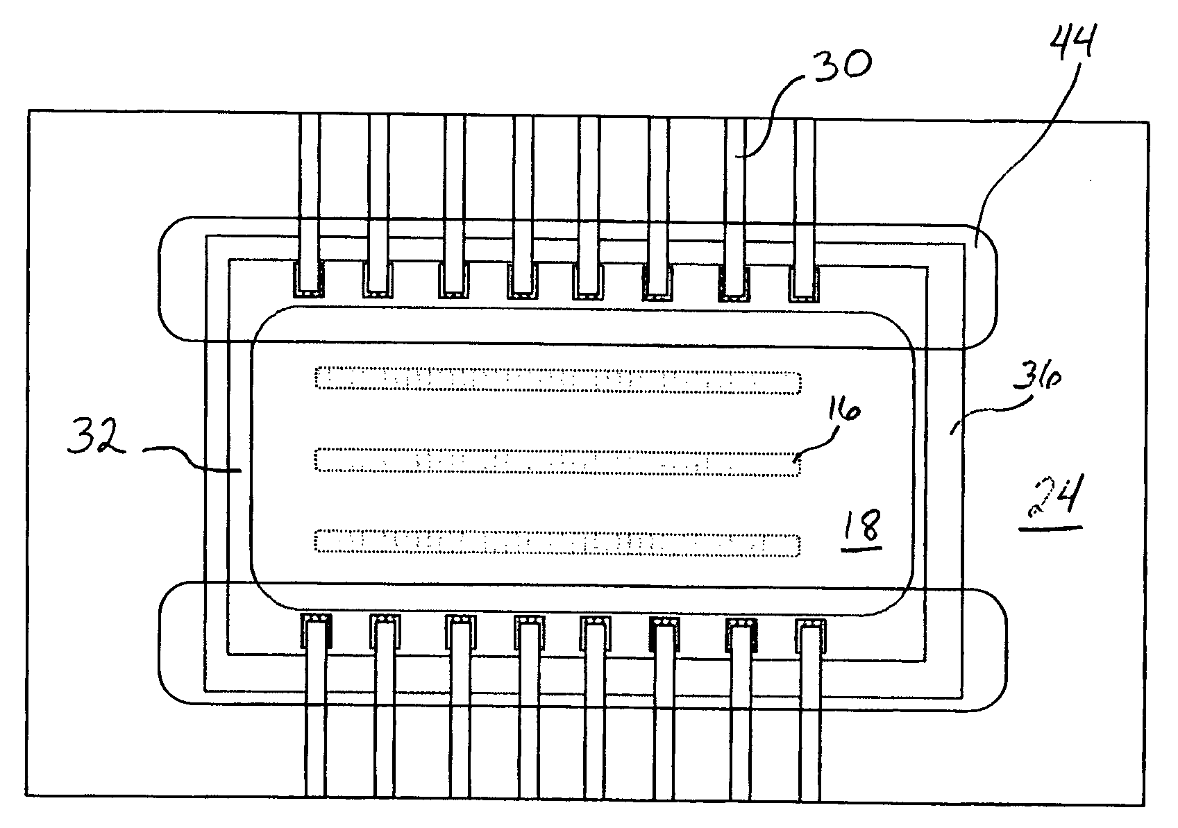
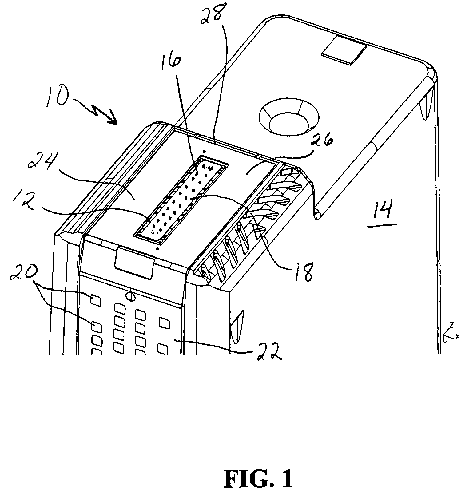
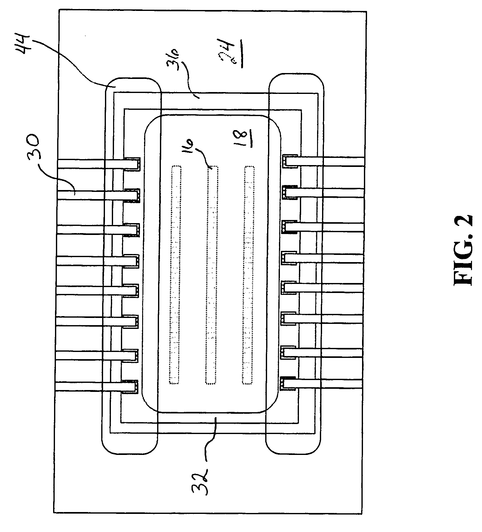
[0017] With reference to FIG. 1, there is shown, in perspective view, an ink jet print cartridge 10 including a heater chip / nozzle plate assembly 12 attached to a cartridge body 14. The cartridge body 14 is an ink-filled polymeric container containing one or more inks for feeding ink to the heater chip / nozzle plate assembly 12 for ejection of ink toward a print media from nozzle holes 16 on nozzle plate 18. Each ink jet print cartridge 10 may contain a single color ink, such as black, cyan, magenta or yellow or may contain multiple colors of ink using a plurality of heater chip / nozzle plate assemblies 12. In the illustration shown in FIG. 1, the ink jet print cartridge 10 contains one heater chip / nozzle plate assembly 12 for ejecting one color of ink.

[0018] In order to cont...


PUM


Abstract

A stencil printed encapsulant material is provided for use in protecting electrical components in thermal ink jet printhead cartridges. A method of applying an encapsulant material to an ink jet print cartridge by stencil printing is also provided. The method includes providing a stencil having at least one aperture, providing an ink jet cartridge and stencil printing an encapsulant material onto a portion of the ink jet print cartridge thereby forming a layer of encapsulant material to protect electrical components or other printhead components.

Description

FIELD OF THE INVENTION [0001] The present invention relates to ink jet printers and, more particularly, to a method of applying an encapsulant material to an ink jet printhead by stencil printing. BACKGROUND OF THE INVENTION [0002] Drop-on-demand ink jet printers use thermal energy to produce a vapor bubble in an ink-filled chamber to expel a droplet. A thermal energy generator or heating element, usually a resistor, is located in the chamber on a heater chip near a discharge orifice. A plurality of chambers, each provided with a single heating element, are provided in the printer's printhead. The printhead typically comprises the heater chip and a nozzle plate having a plurality of the discharge orifices formed therein. The printhead forms part of an ink jet print cartridge which also comprises an ink-filled container. [0003] The resistors are individually addressed with an energy pulse to momentarily vaporize the ink and form a bubble which expels an ink droplet. A flexible circui...

Claims


Application Information

Patent Timeline
IPC IPC(8): B41J2/16B41J2/175
CPCB41J2/14072B41J2/1603B41J2/1754B41J2/1753B41J2/1623
Inventor SMOOT, MARY C.SINGH, JEANNE M. SALDANHASPIVEY, PAUL T.
Owner FUNAI ELECTRIC CO LTD
Why Eureka
Try Eureka