Projection display device
a projection display and display device technology, applied in the field of projection display devices, can solve the problems of reducing the quality of black display and deteriorating contrast performance, and achieve the effect of improving contrast performance and minimizing brightness reduction
- Summary
- Abstract
- Description
- Claims
- Application Information
AI Technical Summary
Benefits of technology
Problems solved by technology
Method used
Image
Examples
first embodiment
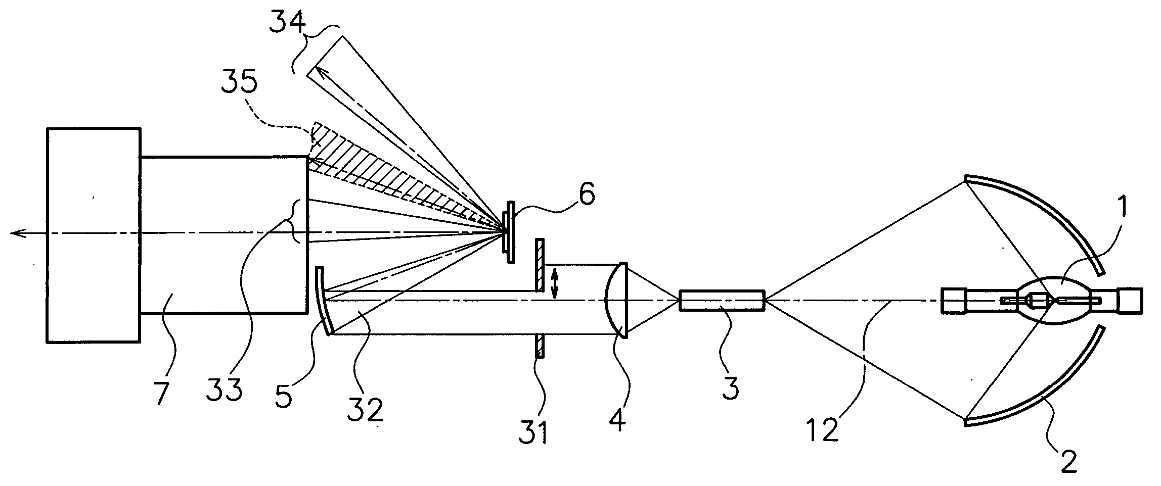
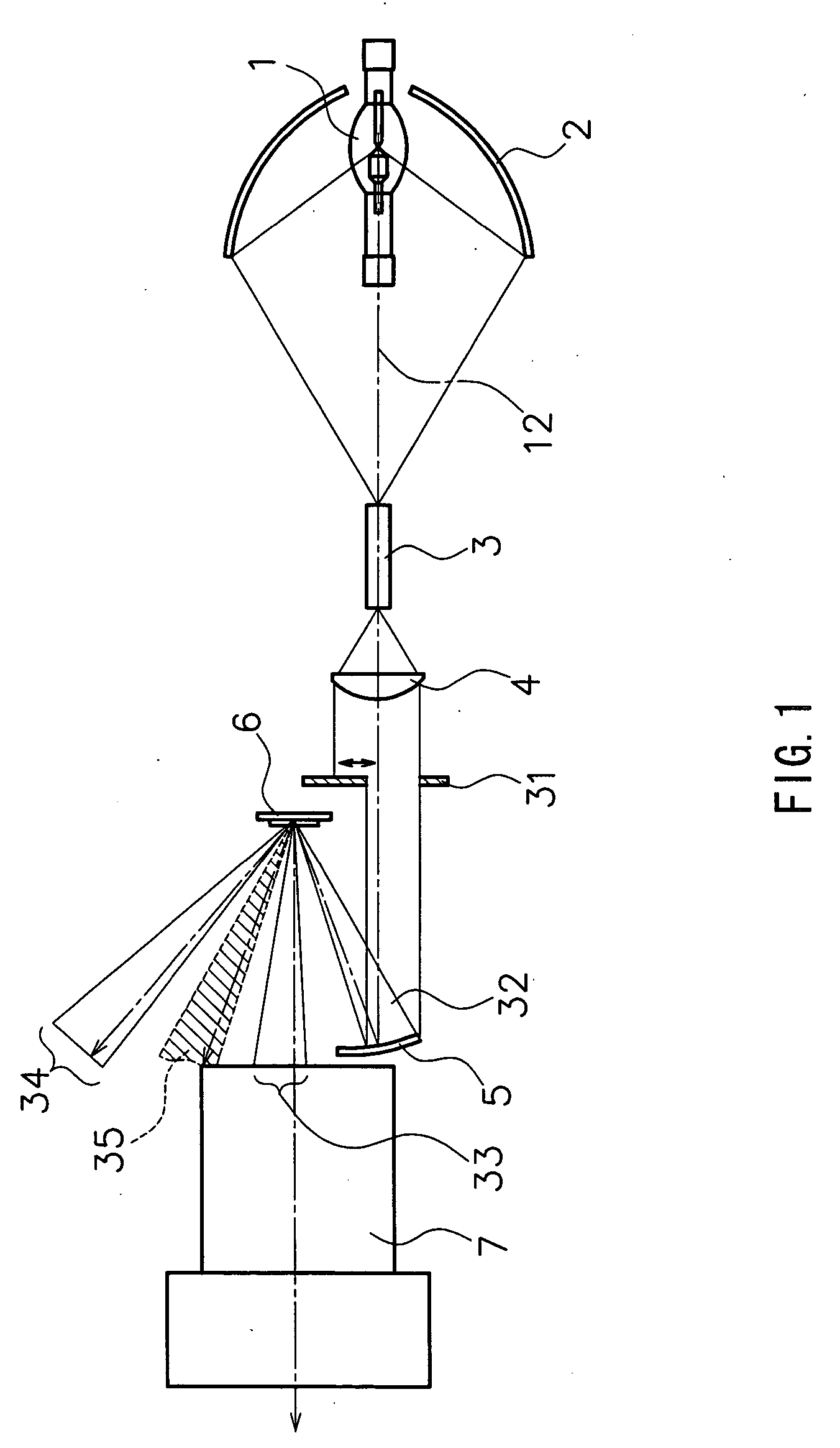
[0045]FIG. 1 shows a schematic configuration of a projection-type display apparatus according to a first embodiment of the present invention. In this figure, numeral 1 denotes a lamp serving as a light source, numeral 31 denotes a diaphragm, numeral 6 denotes a reflecting light valve, and numeral 7 denotes a projection lens. Also, an optical system constituted by a concave mirror 2, a rod prism 3, a condenser lens 4 and a focusing mirror 5 is collectively called an illuminating optical system. Numeral 12 indicates an optical axis of the illuminating optical system.
[0046] The reflecting light valve 6 serving as an image forming member has mirror elements 21 formed in a matrix pattern, each of which corresponds to a pixel, controls a traveling direction of light according to a video signal and forms an optical image by a change in a reflection angle as described referring to FIG. 10. The concave mirror 2 is an elliptical surface mirror that has a reflecting surface with an elliptical...
second embodiment
[0076]FIG. 5 shows a schematic configuration of a projection-type display apparatus according to a second embodiment of the present invention. In this figure, the lamp 1 serving as a light source, the reflecting light valve 6 and the projection lens 7 are equivalent to those shown in FIG. 1. Also, an optical system constituted by a concave mirror 2, a rod prism 3, a condenser lens 4, a reflecting mirror 42, a field lens 43 and a total reflection prism 44 is collectively called an illuminating optical system.
[0077] The concave mirror 2, the rod prism 3 and the condenser lens 4 have the same effects as in the embodiment described referring to FIG. 1, and therefore, the description thereof will be omitted. In the present embodiment, light that has left the condenser lens 4 travels via the reflecting mirror 42 and the field lens 43 and reaches the total reflection prism 44.
[0078] Here, the effect of the total reflection prism 44 will be described. The total reflection prism 44 is cons...
third embodiment
[0086]FIG. 7 shows a schematic configuration of a projection-type display apparatus according to a third embodiment of the present invention. In this figure, the lamp 1 serving as a light source, the reflecting light valve 6 and the projection lens 7 are equivalent to those shown in FIG. 1. Also, as in FIG. 5, a system constituted by a concave mirror 2, a rod prism 3, a condenser lens 4, a reflecting mirror 42, a field lens 43 and a total reflection prism 44 is collectively called an illuminating optical system.
[0087] The concave mirror 2, the rod prism 3 and the condenser lens 4 have the same effects as in the embodiment described referring to FIG. 1, and therefore, the description thereof will be omitted. In the present embodiment, a color separation / combination prism 62 is disposed between the total reflection prism 44 and the reflecting light valve 6, and three reflecting light valves 6 are used.
[0088] In the following, the structure and effect of the color separation / combinat...
PUM
 Abstract
Description
Claims
Application Information
 - R&D
- Intellectual Property
- Life Sciences
- Materials
- Tech Scout
- Unparalleled Data Quality
- Higher Quality Content
- 60% Fewer Hallucinations
Browse by: Latest US Patents, China's latest patents, Technical Efficacy Thesaurus, Application Domain, Technology Topic, Popular Technical Reports.
© 2025 PatSnap. All rights reserved.Legal|Privacy policy|Modern Slavery Act Transparency Statement|Sitemap|About US| Contact US: help@patsnap.com


