
Image forming apparatus

a technology of image forming apparatus and forming tube, which is applied in the direction of electrographic process apparatus, instruments, optics, etc., can solve the problems of difficult to prevent the quality deterioration of printed images, and achieve the effect of efficient collection

Active Publication Date: 2005-04-07
BROTHER KOGYO KK
View PDF10 Cites 13 Cited by
  • Summary
  • Abstract
  • Description
  • Claims
  • Application Information

AI Technical Summary

Benefits of technology

[0008] However, the change of the charge amount of the developer influences not only the transferring process by the transfer body, but also the developing process by the developing device. Accordingly, it is difficult to prevent quality deterioration of the printed image to a sufficient extent by only controlling the transfer bias value depending upon the number of printed paper sheets.
[0009] It is therefore a first object of the present invention to provide an image forming apparatus in which the quality of the printed image is sufficiently prevented from being deteriorated due to an influence of the change in the charge amount of the developer, to thereby form a high-quality image on a recording medium with high stability.
[0010] It is a second object of the present invention to provide an image forming apparatus which is capable of stably forming a high-quality image on a recording medium with reduced power consumption.

Problems solved by technology

However, the change of the charge amount of the developer influences not only the transferring process by the transfer body, but also the developing process by the developing device.
Accordingly, it is difficult to prevent quality deterioration of the printed image to a sufficient extent by only controlling the transfer bias value depending upon the number of printed paper sheets.

Method used


Image

  • Image forming apparatus
  • Image forming apparatus
  • Image forming apparatus

Examples


Embodiment Construction

[0043] Referring to the drawings, there will be described a preferred embodiment of the present invention.

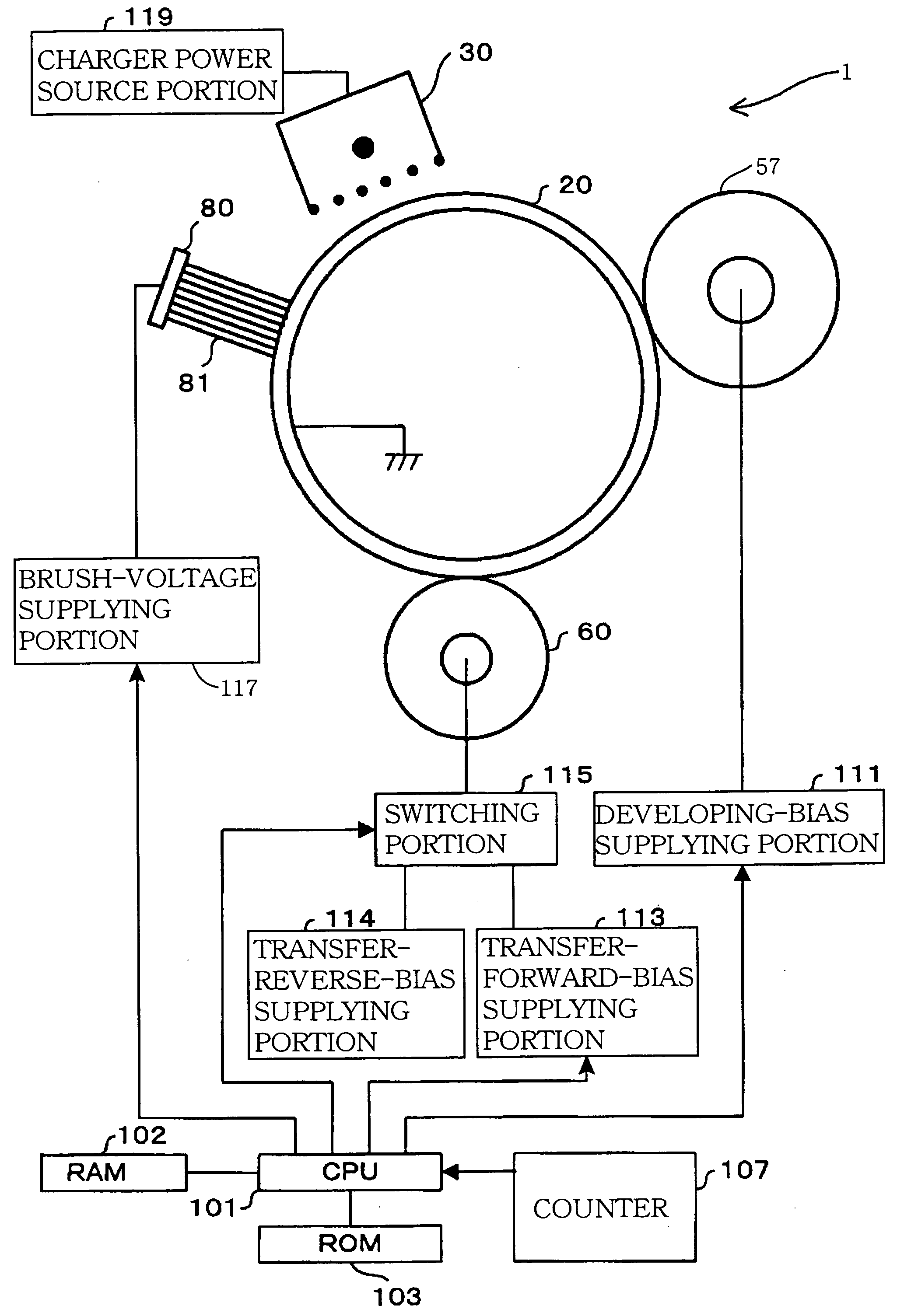
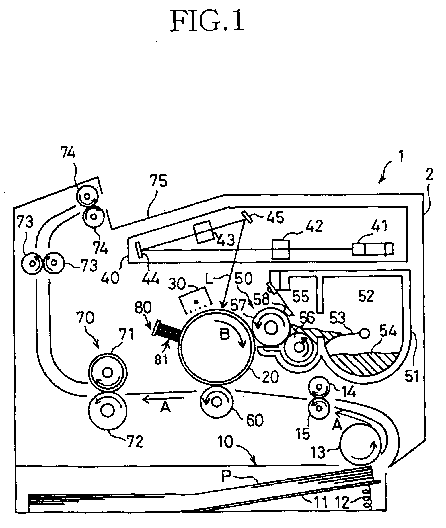
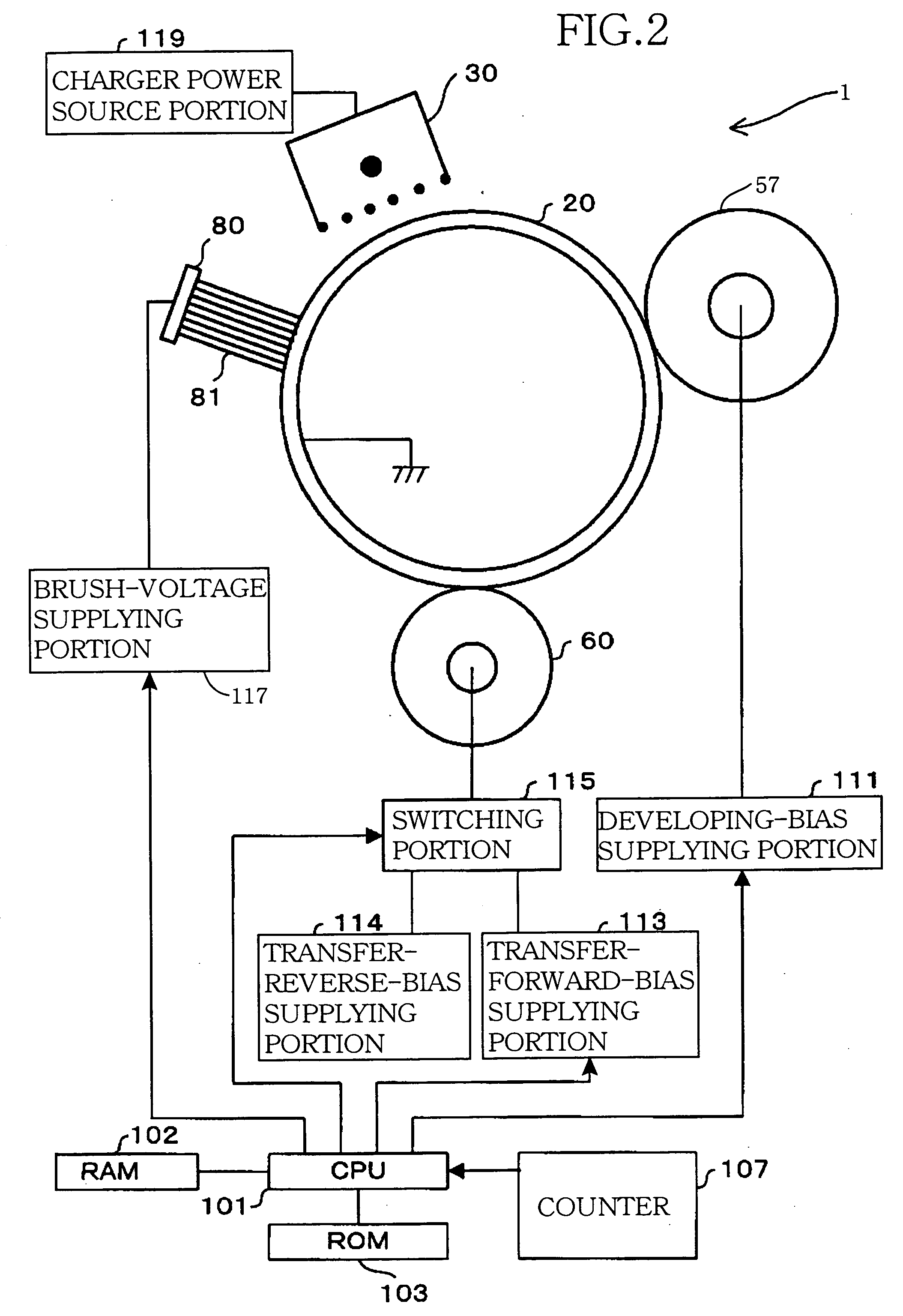
[0044] Referring first to FIG. 1, there is shown an electrophotographic type image forming apparatus in the form of a laser printer indicated at 1 to which the present invention is applied. The laser printer 1 includes a main body casing 2 and a sheet feed unit 10 which is disposed at the bottom of the main body casing 2 and which feeds sheets of recording paper P as the recording media. The sheet feed unit 10 includes a sheet pressing plate 11, a compression spring 12, and a sheet supply roller 13. The sheets of recording paper P stacked on the sheet pressing plate 11 are pressed against the sheet supply roller 13 under the biasing force of the compression spring 12, and an uppermost sheet P is separated from the stack of sheets on the pressing plate 11 by rotation of the sheet supply roller 13, so as to be fed to a pair of the resist rollers 14, 15.

[0045] The resist rollers ...


PUM


Abstract

An image forming apparatus including: a developing device that develops an electrostatic latent image formed on an image bearing body into a visible image by using a charged developer, so as to form a developer image on the image bearing body; a developing-bias supplying device that supplies, to the developing device, a developing bias necessary for developing the electrostatic latent image into the visible image; a transfer device that transfers the developer image formed on the image bearing body onto a recording medium; a transfer-bias supplying device that supplies, to the transfer device, a transfer bias necessary for transferring the developer image onto the recording medium; and a controller that carries out at least one of (A) developing-bias-dependent transfer-bias control for controlling the transfer bias supplied by the transfer-bias supplying device to the transfer device, on the basis of the developing bias supplied by the developing-bias supplying device to the developing device, and (B) operation-amount-dependent developing-and-transfer-bias control for controlling the developing bias supplied by the developing-bias supplying device to the developing device and the transfer bias supplied by the transfer-bias supplying device to the transfer device, on the basis of an operation amount of the image forming apparatus.

Description

[0001] The present application is based on Japanese Patent Application No. 2003-344652 filed Oct. 2, 2003, the contents of which are incorporated herein by reference. BACKGROUND OF THE INVENTION [0002] 1. Field of the Invention [0003] The present invention relates in general to an image forming apparatus which forms a developer image on an image bearing body by developing, with a charged developer, an electrostatic latent image formed on the image bearing body into a visible image, and transfers the developer image to a recording medium. [0004] 2. Discussion of Related Art [0005] As an image forming apparatus, an electrophotographic printer is conventionally known. In this type of image forming apparatus, a photosensitive body as an image bearing or carrying body is exposed to a light to form an electrostatic latent image on the photosensitive body, and a charged developer or developing agent such as toner is applied to the photosensitive body to thereby develop the electrostatic la...

Claims


Application Information

Patent Timeline
Patent Type & Authority Applications(United States)
IPC IPC(8): G03G15/06G03G15/08G03G15/00G03G15/16G03G21/10
CPCG03G15/065G03G2215/1614G03G15/1675
Inventor NISHIMURA, SOICHIRO
Owner BROTHER KOGYO KK
Learn More