Automatic sample analyzer and its components

Inactive Publication Date: 2005-04-07
SYSMEX CORP
View PDF12 Cites 92 Cited by
  • Summary
  • Abstract
  • Description
  • Claims
  • Application Information

AI Technical Summary

Benefits of technology

[0015] In view of the foregoing, it is an object of the present invention to simplify the operation of an automatic sample analyzer for easy handling of the analyzer by doctors and nurses, reduce the size and weight of the analyzer for eas

Problems solved by technology

In addition, the operation of the automatic analyzers is complicated, so that special operators should be employed as

Method used


Image

  • Automatic sample analyzer and its components
  • Automatic sample analyzer and its components
  • Automatic sample analyzer and its components

Examples


Example

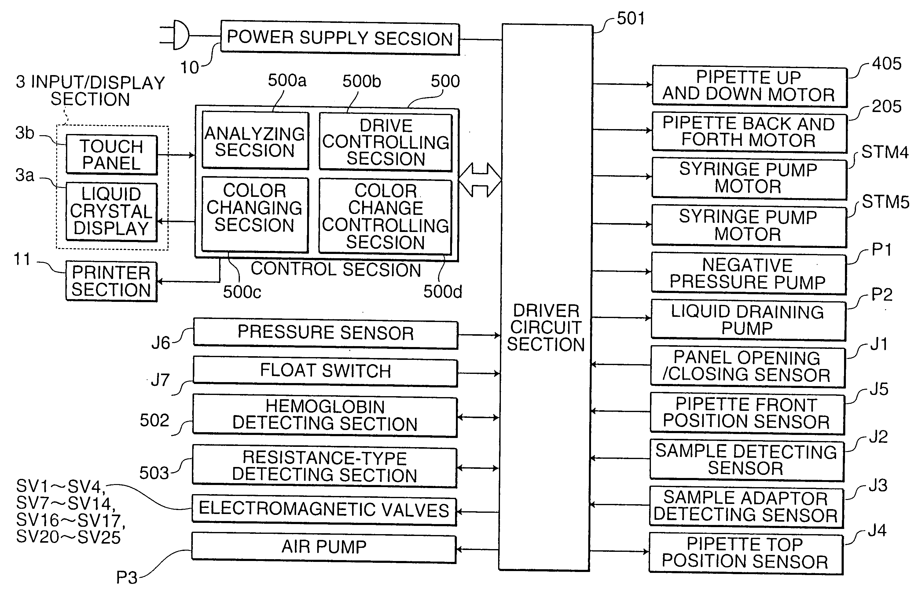
[0094] The automatic sample analyzer according to this invention comprises: a pipette; a pipette driving device which moves the pipette to a sample vessel present in a predetermined position to cause the pipette to suck up a sample from the sample vessel, and then moves the pipette to an open vessel provided in another predetermined position to cause the pipette to discharge the sample into the open vessel; and an analyzing section for analyzing the discharged sample; the pipette driving device comprising a vertically movable main arm and an elongated guide arm cantilevered by the main arm and extending horizontally; the guide arm having a smaller flexural rigidity than the main arm; wherein the main arm vertically moves the pipette when the sample is to be sucked up from the sample vessel, and the guide arm guides the pipette to the open vessel and then vertically moves the pipette when the sample is to be discharged into the open vessel.

[0095] According to this invention, the pip...


PUM


Abstract

An automatic sample analyzer includes: a pipette, a pipette driving device which moves the pipette to a sample vessel present in a predetermined position to cause the pipette to suck up a sample from the sample vessel, and then moves the pipette to an open vessel provided in another predetermined position to cause the pipette to discharge the sample into the open vessel, and an analyzing section for analyzing the discharged sample, the pipette driving device comprising a vertically movable main arm and an elongated guide arm cantilevered by the main arm and extending horizontally, the guide arm having a smaller flexural rigidity than the main arm, wherein the main arm vertically moves the pipette when the sample is to be sucked up from the sample vessel, and the guide arm guides the pipette to the open vessel and then vertically moves the pipette when the sample is to be discharged into the open vessel.

Description

CROSS-REFERENCES TO RELATED APPLICATIONS [0001] This application is a Divisional of co-pending application No. Ser. 10 / 235,955, filed on Sep. 6, 2002, and for which priority is claimed under 35 U.S.C. § 120; the entire contents of which is hereby incorporated by reference. [0002] Further, this application is related to Japanese Patent Application Nos. 2001-270543 (filed on Sep. 6, 2001), 2001-272483 (filed on Sep. 7, 2001), 2001-272484 (filed on Sep. 7, 2001), 2001-272485 (filed on Sep. 7, 2001), 2001-272486 (filed on Sep. 7, 2001), 2001-272487 (filed on Sep. 7, 2001), 2001-275375 (filed on Sep. 11, 2001), 2001-275385 (filed on Sep. 11, 2001), 2001-275397 (filed on Sep. 11, 2001), 2001-355093 (filed on Nov. 20, 2001), 2001-362979 (filed on Nov. 28, 2001), 2002-108113 (filed on Apr. 10, 2002) and 2002-126640 (filed on Apr. 26, 2002); whose priorities are claimed under 35 U.S.C. § 119, the disclosures of which are incorporated by reference in their entirety.BACKGROUND OF THE INVENTION...

Claims


Application Information

Patent Timeline
IPC IPC(8): G01N1/00G01N33/483G01N35/10
CPCG01N15/12G01N35/1002G01N35/1004G01N35/1079G01N2035/00524G01N2015/0073G01N2015/008G01N2015/1006G01N2015/1062G01N35/1083G01N35/10
Inventor TANOSHIMA, EIJISAKURAI, KAZUYUKI
Owner SYSMEX CORP
Why Eureka
Try Eureka