
Multimode receiver and method for controlling signal interference

a multi-mode receiver and interference control technology, applied in the direction of transmission monitoring, line-fault/interference reduction, amplitude demodulation, etc., can solve the problems of increasing the power consumption of the wireless device, increasing the generation of the interference product signal, and increasing the system interferen

Active Publication Date: 2005-04-07
GOOGLE TECH HLDG LLC
View PDF16 Cites 110 Cited by
  • Summary
  • Abstract
  • Description
  • Claims
  • Application Information

AI Technical Summary

Problems solved by technology

Further, as the number of multimode wireless devices communicating in a wireless communication system increases, system interference also generally increases.
However, since only one receiver is used during normal operation, the single receiver wireless device cannot simultaneously receive a wireless signal and detect an interference blocking signal causing the generation of the interference product signal.
Additionally, increasing the linearity or spurious free dynamic range of the LNA increases power consumption within the wireless device.
Accordingly, such a method is limited to increasing the linearity or spurious free dynamic range of the low noise amplifier in a single receiver wireless device.
However, one receiver does not simultaneously receive a wireless signal while the other receiver detects a blocking interference source.
Further, such a multimode wireless transceiver cannot operate simultaneously to receive a wireless signal while the second receiver detects the blocking interference source without causing a degradation of performance in one or the other receiver.

Method used


Image

  • Multimode receiver and method for controlling signal interference
  • Multimode receiver and method for controlling signal interference
  • Multimode receiver and method for controlling signal interference

Examples


Embodiment Construction

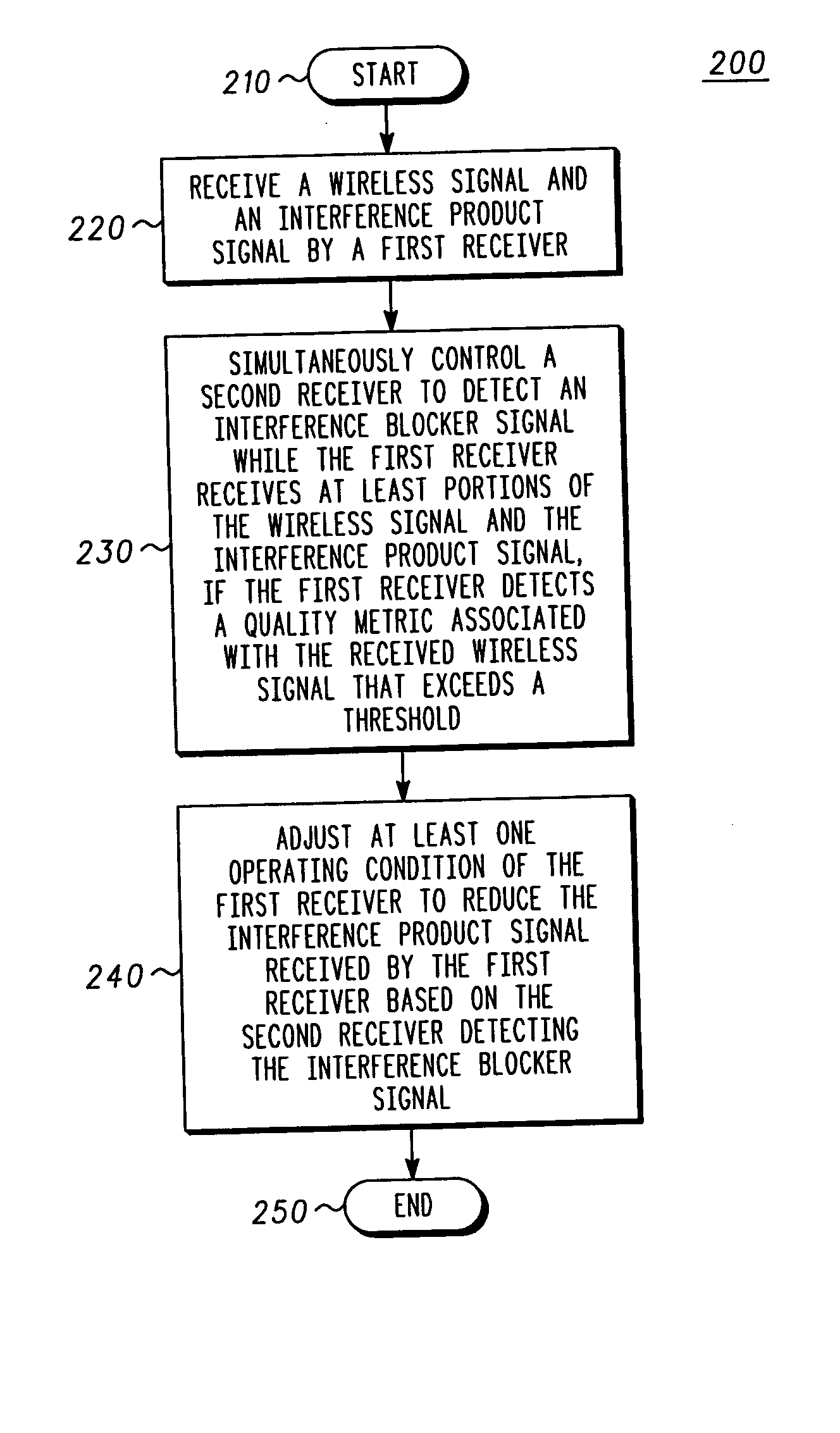
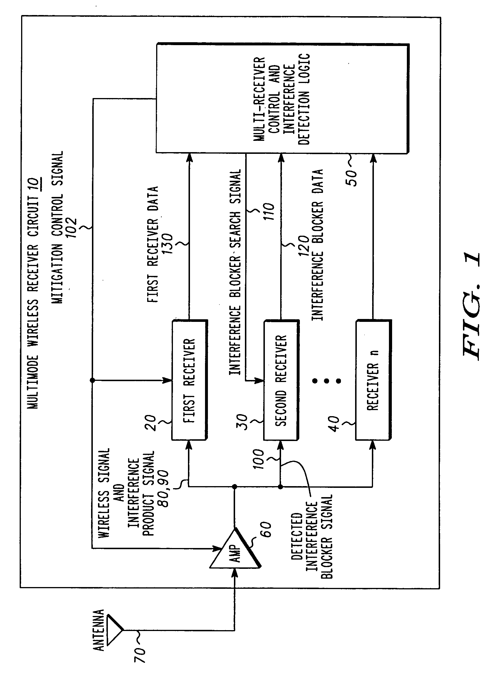
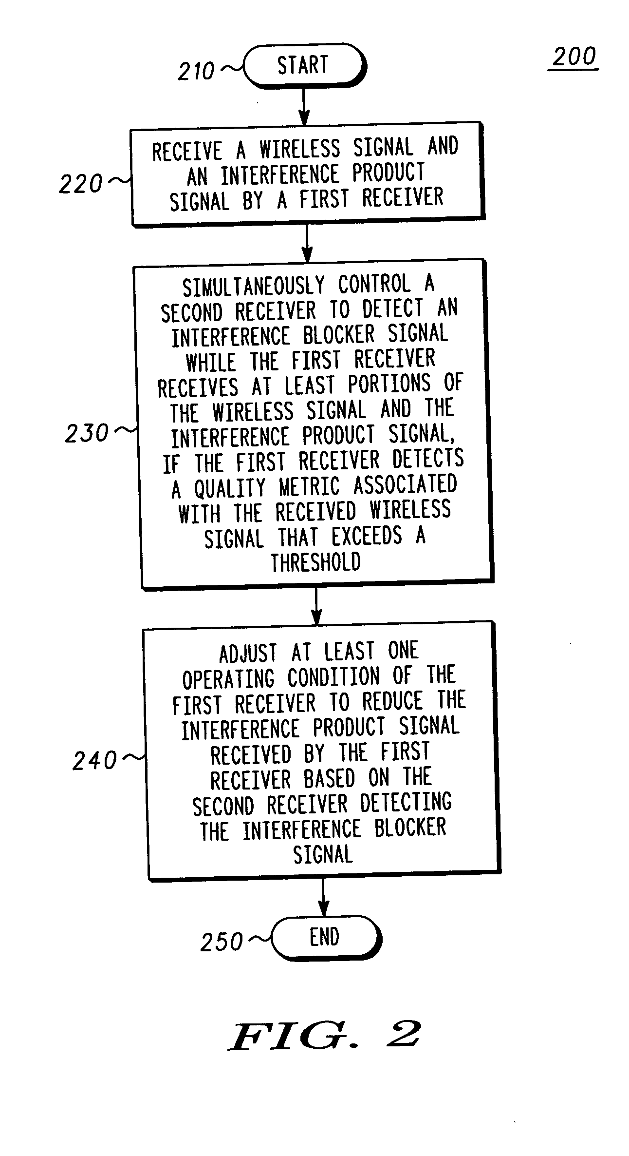
[0011] A multimode wireless receiver circuit includes multi-receiver control and interference detection logic and at least two separate receivers: a first receiver associated with a first radio access technology and a second receiver associated with a second radio access technology. The first and second radio access technologies may be, for example, W-CDMA and GSM technologies or any other suitable technologies. The multi-receiver control and interference detection logic simultaneously controls the second receiver to detect an interference blocker signal, while the first receiver receives at least a portion of a wireless signal and an interference product signal. For example, the multi-receiver control and interference detection logic may cause the second receiver to tune to a frequency, or scan a band of frequencies, in order to determine if an interference blocker signal exists. In response to the second receiver's detecting an interference blocker signal, the multi-receiver contr...


PUM


Abstract

A multimode wireless receiver circuit (10) includes multi-receiver control and interference detection logic (50) and least two separate receivers: a first receiver (20) associated with a first radio access technology and a second receiver (30) associated with a second radio access technology. The multi-receiver control and interference detection logic (50) simultaneously controls the second receiver (30) to detect an interference blocker signal (100), while the first receiver (20) receives at least a portion of the wireless signal (80) and the interference product signal (90). In response to the second receiver (30) detecting the interference blocker signal (100), the multi-receiver control and interference detection logic (50) adjusts at least one operating condition of the first receiver (20) such that the interference product signal (90) received by the first receiver (20) is reduced.

Description

FIELD OF THE INVENTION [0001] The invention relates generally to wireless communication devices and methods and more particularly to a wireless device and method for mitigating interference. BACKGROUND OF THE INVENTION [0002] The recent emergence of second-generation, third-generation and higher wireless communication systems creates a need for wireless communication devices capable of accessing multiple communication systems with different radio access technologies within one or more wireless frequency bands. For example, the emergence of various communications standards has driven the need for wireless communication devices, such as wireless telephones, and other types of wireless devices, to be capable of accessing multiple communication systems employing different radio access technologies such as, for example, a global system for mobile communications (GSM) and wideband code division multiple access (W-CDMA) communication systems serving a common geographical area. The multimod...

Claims


Application Information

Patent Timeline
IPC IPC(8): H04B1/10H04B1/40
CPCH04B1/406H04B1/1027
Inventor MACH, RICHARDHAUB, DAVIDKURBY, CHRISTOPHERVANNATTA, LOUIS
Owner GOOGLE TECH HLDG LLC
Learn More