Two-stage attachment for cutting, crimping etc, and mechanical method thereof

Active Publication Date: 2005-04-14
BRAILOVSKIY ALEKSANDR M
View PDF21 Cites 22 Cited by
  • Summary
  • Abstract
  • Description
  • Claims
  • Application Information

AI Technical Summary

Benefits of technology

[0017] A primary object of the present invention is to introduce an attachment that is readily adaptable to existing and available force multiplying devices as well as to those yet to come, regardless of their being either manual or with power source.
[0018] Two-stage attachment must utilize an approach not found in it's full scope in the prior art of the related field. It shall combine, to a maximal extend, beneficial qualities of prior art and those newly suggested hereby, while keeping sacrifices to a minimum.
[0035] 6) Accomplishing higher degree of adaptability than that available from the prior art tools, i.e., making the attachment suitable for use with a plurality of the force multiplying devices, both manual and with power source, even those made by competing manufacturers, so that one can purchase the attachment and readily use it with, for example, his/her old bolt cutter handles.
[0036] The objects and advantages of the present invention are not limited to above listed. Other benefits

Problems solved by technology

It is, however, rather function specific, hence being unable to help minimizing the amount of hardware that one must acquire and maintain in a course of doing business.
Moreover, most of tools that are designed for performing a certain duty do not provide for any versatility even within a definition of such duty.
For instance, two separate tools usually had to be purchased in the past, one for cutting metal rods or bolts and another for cutting cables, since well known bolt cutters with straight edge jaws perform on cables very poorly.
Further, shearing blades enclosed inside one another generate width exceeding that of “squeezing / crushing” cutters, adding limitation to the tool's usefulness.
Considering structural properties of materials involved, a tool's width herein must somewhat exceed that of most prior and current art, thus restricting it's use in narrow openings (such as between pipe flange faces).
Also, as a “penalty”for use of fully circular eccentrically pivoted boss (to multiply the force), this tool's handles must be opened to a notably greater angle, thus practically nullifying a benefit of their being shorter, but making them unsafe and uncomfortable instead.
A lack of inexpensive and easily replaceable blades also remains as in most existing tools.
Nevertheless, eventually one still has to replace blades that do cost nearly as much as a whole new tool.
The issue of replaceable blades was specifically addressed by inventions of EP0011545 to Muller, May 28, 1980 (FIG. 4A) and U.S. Pat. No. 5,898,998 to Deville, May 4, 1999 (FIG. 4B), but the solution suggested therein, while being suitable for usage in many of tool designs, is not entirely satisfactory.
It weakens a blade support and does not facilitate a uniform transfer and distribution of tensions within a metal structure of the blade and the blade support, thus speeding up an accumulation of a fatigue in the structure.
In exchange, this improvement renders such cutter practically incapable of cutting anything thinner then, roughly, a width of a gap between jaws opened to about two-thirds of their capacity.
But such attachments shall come at relatively high cost and, except JP02002078988, would very doubtfully be easily demountable.

Method used


Image

  • Two-stage attachment for cutting, crimping etc, and mechanical method thereof
  • Two-stage attachment for cutting, crimping etc, and mechanical method thereof
  • Two-stage attachment for cutting, crimping etc, and mechanical method thereof

Examples


Embodiment Construction

—FIGS. 6 TO 14K.

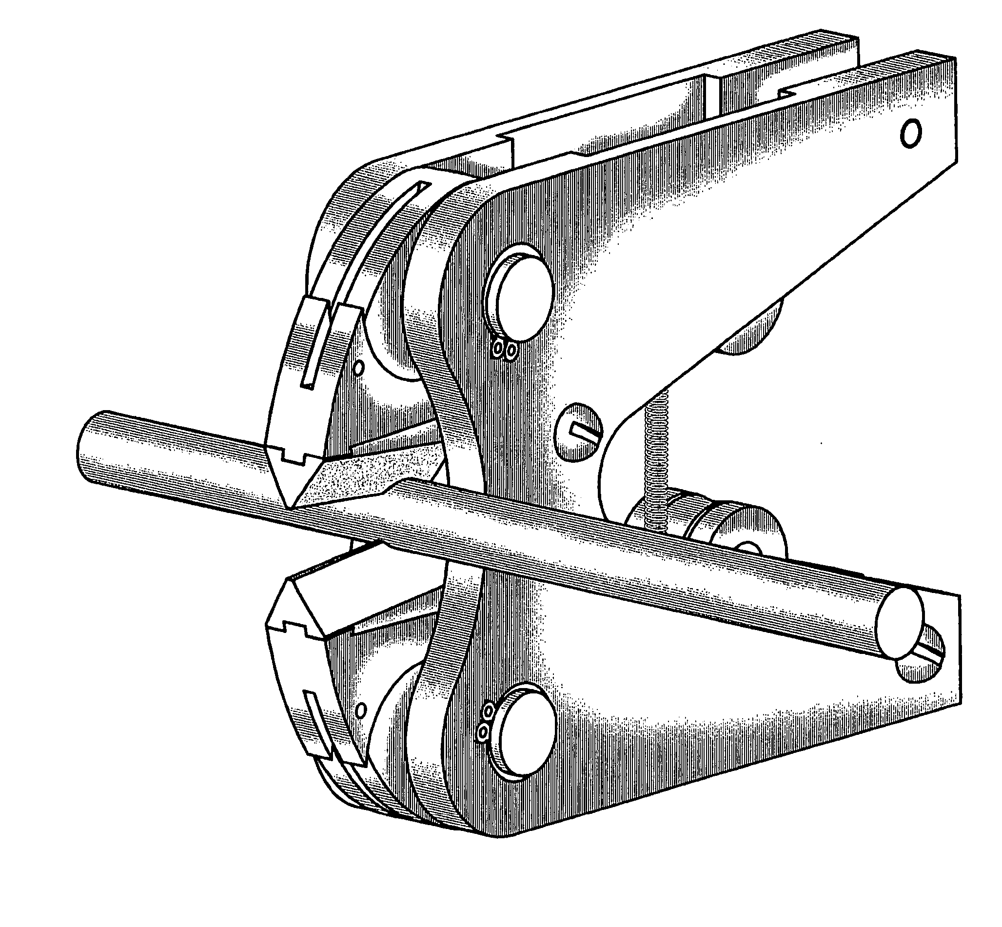
[0118] A preferred embodiment of Two-stage attachment comprises two sectorial, as opposed to fully circular or elliptical, eccentrically pivoted cams, or cams 15a and 15b. Each of these cams is made as one piece with it's respective lever, namely levers 16a and 16b so that each cam and it's lever have one common pivot, or master pivot. Each of two master pivots 17a and 17b, in it's turn, consists of right and left master pivot shafts, accordingly, 17Ra, 17La, 17Rb and 17Lb.

[0119] Rear end of each of levers 16a and 16b forks into two coaxial vertically oriented pad eyes, shown as 16Ra, 16La, 16Rb and 16Lb, and rollers 18a and 18b are accommodated between these pad eyes. Outer rim surface of each of rollers 18a and 18b has shallow groove of triangular profile. Roller's axis 19a and 19b respectively are inserted through pad eyes 16 Ra, 16La, 16Rb and 16Lb and being kept at place by retaining screws 20 (same numeral for all four).

[0120] On both sides of levers 16a and ...


PUM

PropertyMeasurementUnit
Forceaaaaaaaaaa
Distanceaaaaaaaaaa
Tensionaaaaaaaaaa

Abstract

A multifunctional tool for cutting (crushing or shearing), crimping, perforating and other operations that require high force to be applied to a small area, plus a method of designing such tools for a variety of applications. A sectorial eccentrically pivoted cam is implemented as a part of a lever of first stage. A working surface of this cam fits precisely onto a corresponding surface of a lever of a second stage so that when the cam is partially rotated about its pivot, the lever of second stage receives impetus to move about its own pivot at hyperbolic trajectory and a distance lesser than that of the lever of first stage.

Description

CROSS-REFERENCE TO RELATED APPLICATIONS [0001] This application claims the priority to U.S. Provisional Patent Application No. 60 / 510,166 filed on Oct. 8, 2003FEDERALLY SPONSORED RESEARCH [0002] None. SEQUENCE LISTING [0003] None. BACKGROUND OF THE INVENTION [0004] This invention is related to a field of tools used by various industries, more particularly of those for cutting metal rods, bolts, cables and like, crimping and other operations for which severing or squeezing force is essential. [0005] The art currently existing in this field is very prolific and ingenious. It is, however, rather function specific, hence being unable to help minimizing the amount of hardware that one must acquire and maintain in a course of doing business. Moreover, most of tools that are designed for performing a certain duty do not provide for any versatility even within a definition of such duty. [0006] Versatility never comes without a sacrifice of some of the merits immanent to single-purpose imple...

Claims


Application Information

Patent Timeline
IPC IPC(8): B25B7/12B25B27/10B26B17/02
CPCB25B7/126B25B27/10B26B17/02B23D17/02B23D29/023H01R43/042B26F1/36B23D29/002B23D29/00
Inventor BRAILOVSKIY, ALEKSANDR M.
Owner BRAILOVSKIY ALEKSANDR M
Why Eureka
Try Eureka