Aluminum alloy smelting automatic feeding tower and automatic feeding method thereof

An aluminum alloy, melting furnace technology, applied in chemical instruments and methods, cleaning methods and utensils, cleaning methods using liquids, etc. Avoid clogging of valve ports, improve the problem of poor combustion efficiency, and have the effect of strong use reliability

Inactive Publication Date: 2022-02-08
钱军
View PDF0 Cites 0 Cited by
  • Summary
  • Abstract
  • Description
  • Claims
  • Application Information

AI Technical Summary

Problems solved by technology

[0003] The existing feeding towers for aluminum alloy smelting are mostly based on program programming, and then operate the aluminum particle cutting at a specific time and under specific working conditions. In the actual operation process, it is difficult to carry out self-adaptive lowering according to the actual smelting conditions. Material, that is, in aluminum alloy smelting, the relationship between the amount of material in the smelting furnace and the exhaust gas temperature is not properly utilized, which makes it difficult for the feeding tower to match the corresponding amount of material in the furnace in real time, and calmly causes the smelting furnace to fail. Dry burning, or too much material in the furnace body, it is difficult to fully melt the aluminum particles

Method used


Image

  • Aluminum alloy smelting automatic feeding tower and automatic feeding method thereof
  • Aluminum alloy smelting automatic feeding tower and automatic feeding method thereof
  • Aluminum alloy smelting automatic feeding tower and automatic feeding method thereof

Examples


Embodiment 1

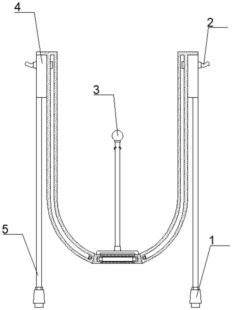
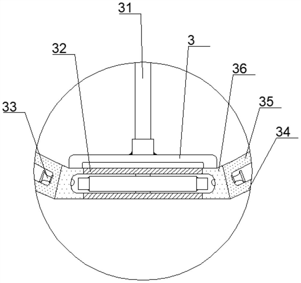
[0035] like Figure 1-2As shown, the aluminum alloy smelting automatic feeding tower includes a feeding assembly 3 and an evaporating assembly 4. The evaporating assembly 4 is fixedly connected to both sides of the feeding assembly 3. The outer wall of the evaporating assembly 4 is embedded with a sleeve, and the sleeve is socketed. There are water pipes 2; two supporting pipes 5 are symmetrically fixed at the bottom of the evaporation assembly 4, and the bottom of the supporting pipes 5 is fixedly connected with a smoke guide pipe 1, and the smoke guide pipe 1 is plugged and fixed to the top wall of the melting furnace; the feeding assembly 3 includes Vibrating part 31, valve part 32, nozzle 33, outer barrel 34, inner barrel 35 and air guide seat 36, inner barrel 35 is set in the outer barrel 34, the upper and lower annular edges of inner barrel 35 and outer barrel 34 are fixedly connected; inner barrel 35 and An air guide seat 36 is sleeved on the connected lower annular edg...

Embodiment 2

[0039] like Figure 2-7 As shown in the automatic feeding tower for aluminum alloy smelting, the valve member 32 includes an upper circular plate 321, a spacer bar 322, a blocking unit 323, a lower circular plate 324 and a reset unit 325, and an upper circular plate 321 and a lower circular plate 321 are arranged in the air guide seat 36. Plate 324, the surface of upper circular plate 321 and lower circular plate 324 are all run through and be provided with semicircle slot position; The upper circular edge is connected, and the outer edge of the lower circular plate 324 is connected with the lower circular edge of the air guiding seat 36; a barrier unit 323 is arranged between the upper circular plate 321 and the lower circular plate 324, and the barrier unit 323 is covered with a spacer bar 322 , the upper and lower ends of the spacer bar 322 are fixedly connected to the center of the upper circular plate 321 and the lower circular plate 324; one side of the spacer bar 322 is...

Embodiment 3

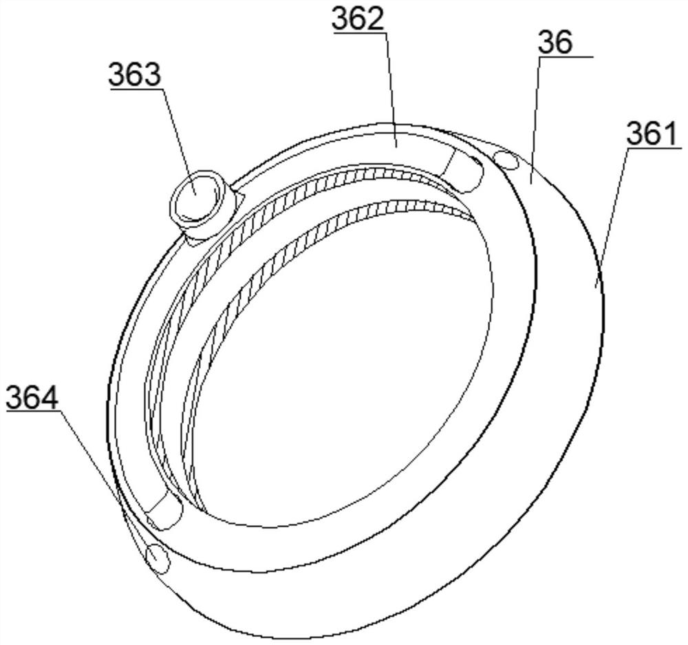
[0045] like figure 1 , 2 , 7 and 8, in the aluminum alloy smelting automatic feeding tower, the air guide seat 36 includes a double-layer ring seat 361, a half-ring pipe 362, a pipe seat 363 and a socket 364, and the lower annular edge of the inner barrel 35 and the outer barrel 34 A double-layer ring seat 361 is sleeved, and the two sides of the double-layer ring seat 361 are provided with a jack 364, and the nozzle 33 is set inside the jack 364; The two ends of the tube are fixedly connected with vertical tubes, and the vertical tubes are inserted into the double-layer ring seat 361; the top side of the half-ring tube 362 is connected with a tube seat 363, and the vibrating member 31 is sleeved and fixed in the tube seat 363.

[0046] The vibrating element 31 includes a sphere 311, a row pipe 312, an elbow nozzle 313 and a firing unit 314. The row pipe 312 is plugged and fixed to the air guide seat 36. A sphere 311 is arranged inside the row pipe 312. The diameter of the sp...


PUM


Abstract

The invention provides an aluminum alloy smelting automatic feeding tower and an automatic feeding method thereof, and relates to the field of feeding machine.The aluminum alloy smelting automatic feeding tower comprises a feeding assembly and evaporation assemblies, wherein the evaporation assemblies are fixedly connected to the two sides of the feeding assembly, sleeve bases are embedded into the outward wall bodies of the evaporation assemblies in a penetrating mode, and water pipes are connected into the sleeve bases in a sleeved mode; two supporting pipes are symmetrically fixed to the bottom end of each evaporation assembly, smoke guiding pipes are fixedly connected to the bottom ends of the supporting pipes, and the smoke guiding pipes are inserted and fixed to the top wall of the smelting furnace; the feeding assembly comprises a vibration part, a valve part, a spray head, an outer barrel, an inner barrel and an air guide base, wherein the inner barrel is sleeved by the outer barrel, the opening and the opening degree of the valve part are adjusted, and manual intervention is not needed in the adjusting process; and compared with traditional program control, the aluminum alloy smelting automatic feeding tower has the advantages of being high in self-adaption degree, high in use firmness and the like; and the problem of poor combustion efficiency caused by dry burning in the smelting furnace or excessive materials in the furnace can be greatly improved.

Description

technical field [0001] The invention relates to the field of feeding machinery, in particular to an automatic feeding tower for aluminum alloy smelting and an automatic feeding method thereof. Background technique [0002] Feeding machinery is to automatically inject materials into the melting furnace, so that the melting furnace is always in a state of high fuel efficiency. Currently, feeding machinery mainly includes claw feeders, hopper feeders, etc. [0003] The existing feeding towers for aluminum alloy smelting are mostly based on program programming, and then operate the aluminum particle cutting at a specific time and under specific working conditions. In the actual operation process, it is difficult to carry out self-adaptive lowering according to the actual smelting conditions. Material, that is, in aluminum alloy smelting, the relationship between the amount of material in the smelting furnace and the exhaust gas temperature is not properly utilized, which makes i...

Claims


Application Information

Patent Timeline
IPC IPC(8): F27B14/16B08B3/02F27D17/00F22B1/18
CPCF27B14/0806B08B3/02F27D17/004F22B1/18F27B2014/0812
Inventor 钱军
Owner 钱军
Why Eureka
Try Eureka