
Railway wagon cab apron falling fault identification method

A railway freight car and fault identification technology, applied in neural learning methods, character and pattern recognition, instruments, etc., can solve the problems of railway freight car ferry plate falling off, fault detection accuracy and low efficiency, and achieve edge integrity and self-adaptation High, accurate results

Active Publication Date: 2021-06-15
HARBIN KEJIA GENERAL MECHANICAL & ELECTRICAL CO LTD
View PDF7 Cites 0 Cited by
  • Summary
  • Abstract
  • Description
  • Claims
  • Application Information

AI Technical Summary

Problems solved by technology

[0004] The purpose of the present invention is to propose a fault identification method for the fall-off of the ferry board of a railway freight car in order to solve the problems of low accuracy and low efficiency of fault detection in the existing manual fault detection method

Method used


Image

  • Railway wagon cab apron falling fault identification method
  • Railway wagon cab apron falling fault identification method
  • Railway wagon cab apron falling fault identification method

Examples


specific Embodiment approach 1

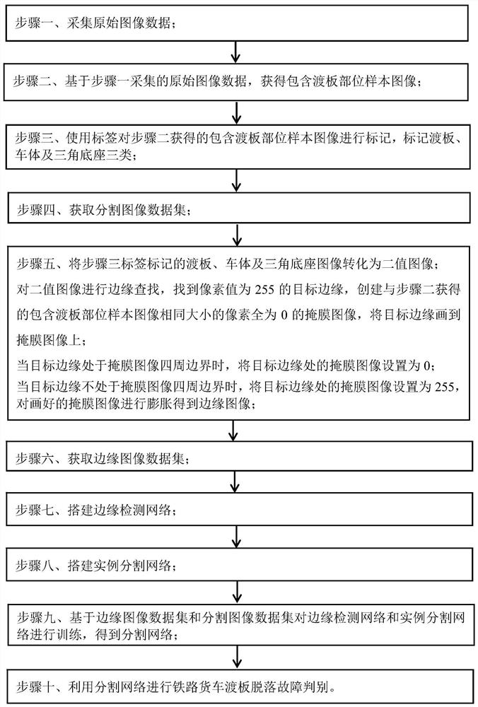
[0072] Specific implementation mode one: combine figure 1 Describe this embodiment, the specific process of a kind of fault identification method that the ferry plate of railway wagon falls off in this embodiment is:

[0073] Step 1, collecting original image data;

[0074] Step 2, based on the original image data collected in step 1, obtain a sample image including the part of the transition plate;

[0075] Step 3. Use tags to mark the sample image including the transition plate part obtained in step 2, and mark the three types of transition plate, car body and triangular base;

[0076] Since the angle of the camera at different stations and the distance between the camera and the car body will be different, a fixed part is required for pixel calibration; the position and posture of the ferry board are easy to change, but the position of the triangular base supporting the ferry board is fixed and cannot be moved. Therefore, in order to unify the fault standard, mark the tri...

specific Embodiment approach 2

[0089] Specific embodiment two: the difference between this embodiment and specific embodiment one is that the original image data is collected in step one; the specific process is:

[0090] Set up high-speed imaging equipment at a fixed detection site to obtain 2D high-definition linear array grayscale images of trucks, and select images taken by the camera above the side of the truck (used at the same time on the left and right) as the original image; long-term image collection, to obtain images taken at different sites and under different conditions For the original image, different conditions refer to images with various natural disturbances such as light, rain, etc. in the image to ensure the diversity of the data, so that the final model will have better robustness.

[0091] Other steps and parameters are the same as those in Embodiment 1.

specific Embodiment approach 3

[0092] Specific embodiment 3: The difference between this embodiment and specific embodiment 1 or 2 is that in step 2, based on the original image data collected in step 1, a sample image including the transition plate is obtained; the specific process is:

[0093] According to the prior knowledge and the wheelbase information provided by the hardware and framework (data acquisition equipment such as sensors), the original image is intercepted to obtain a sample image including the transition plate.

[0094] Other steps and parameters are the same as those in Embodiment 1 or Embodiment 2.


PUM


Abstract

The invention relates to a fault identification method for fall-off of a cab apron of a railway wagon. The invention relates to the fault identification method for fall-off of the cab apron of the railway wagon. The objective of the invention is to solve the problems of low fault detection accuracy and low efficiency of an existing method. The method comprises the following steps: 1, acquiring original image data; 2, obtaining a sample image containing a cab apron part; 3, marking a cab apron, a vehicle body and a triangular base; 4, obtaining a segmented image data set; 5, drawing the edge of the target on the mask image; when the target edge is located at the peripheral boundary of the mask image, setting the mask image at the target edge as 0; otherwise, setting the mask image at the target edge as 255, and expanding the mask image to obtain an edge image; 6, acquiring an edge image data set; 7, establishing an edge detection network; 8, building an instance segmentation network; 9, obtaining a segmentation network; 10, carrying out railway wagon cab apron falling fault judgment by utilizing the segmentation network. The invention belongs to the field of fault image recognition.

Description

technical field [0001] The invention relates to a fault identification method for the fall-off of a ferry plate of a railway freight car. Background technique [0002] In the direction of railway safety, the traditional method is to find the fault point of the train through manual observation after the detection equipment takes pictures. This approach enables fault detection while the vehicle is moving without stopping. However, manual observation has disadvantages such as fatigue, high intensity, and need for training. At this stage, more and more things can be replaced by machines. Machines have the characteristics of low cost, unified rules, and 24-hour fatigue-free. Therefore, it is feasible to use image recognition technology to replace traditional manual inspection. [0003] It is difficult for the human eye to accurately judge the distance, and the different sizes of the targets photographed at different sites make it more difficult to detect with the human eye. Us...

Claims


Application Information

Patent Timeline
Patent Type & Authority Applications(China)
IPC IPC(8): G06K9/00G06K9/34G06K9/46G06N3/04G06N3/08
CPCG06N3/08G06V20/20G06V10/26G06V10/44G06N3/045
Inventor 汤岩
Owner HARBIN KEJIA GENERAL MECHANICAL & ELECTRICAL CO LTD
Learn More