Method and apparatus for detecting guideway breaks and occupation

a guideway and break technology, applied in the field of track detection systems, can solve the problems of burdening the cost per mile of new track installation, small separation gap at the break, and existing external detection system requires significant wayside infrastructur

Inactive Publication Date: 2005-04-14
ANALOGIC ENG
View PDF11 Cites 57 Cited by
  • Summary
  • Abstract
  • Description
  • Claims
  • Application Information

AI Technical Summary

Problems solved by technology

A mechanical failure of a rail often leads to a small separation gap at the break because the rail is typically in tension at low to average temperatures.
As can be imagined, the existing external detection system requires significant wayside infrastructure for every relatively short block of track.
The signal generation circuitry, detection circuitry and the indicator lights require electrical power and are often located in remote and sometimes difficult to reach locations.
The cost per mile of new track installation is burdened by the capital outlay for signaling equipment and interconnecting cabling, additional construction and installation expense, and costs associated with providing electrical power at regular intervals along the track.
In operation, the wayside infrastructure has high maintenance and upkeep costs per mile of track.
Signaling equipment is subjected to extreme temperatures and poor weather conditions, and is susceptible to equipment failures that sometimes lead to expensive traffic delays.
For example, CBTC would not protect against collisions involving non-CBTC track occupation such as an unexpected detached railcar.

Method used


Image

  • Method and apparatus for detecting guideway breaks and occupation
  • Method and apparatus for detecting guideway breaks and occupation
  • Method and apparatus for detecting guideway breaks and occupation

Examples


Embodiment Construction

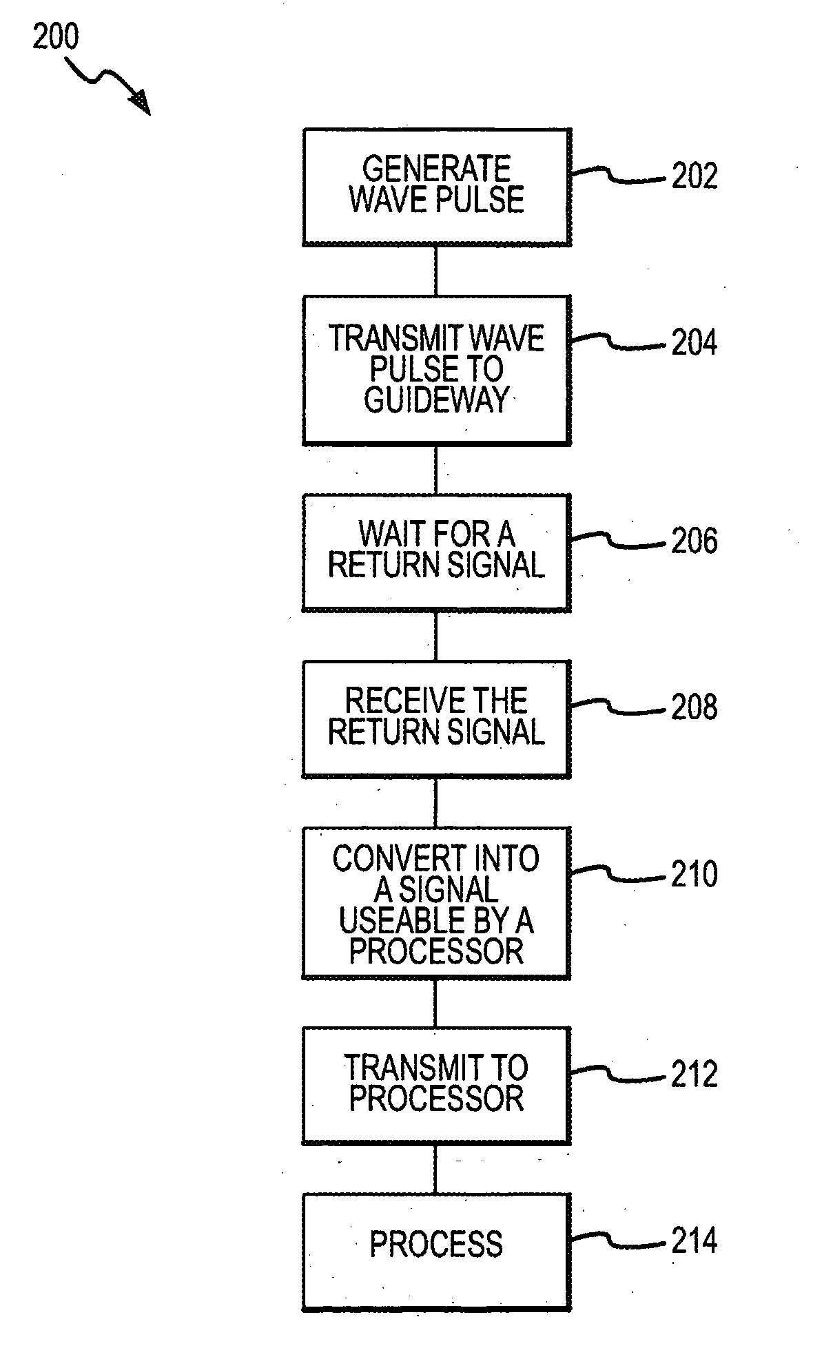
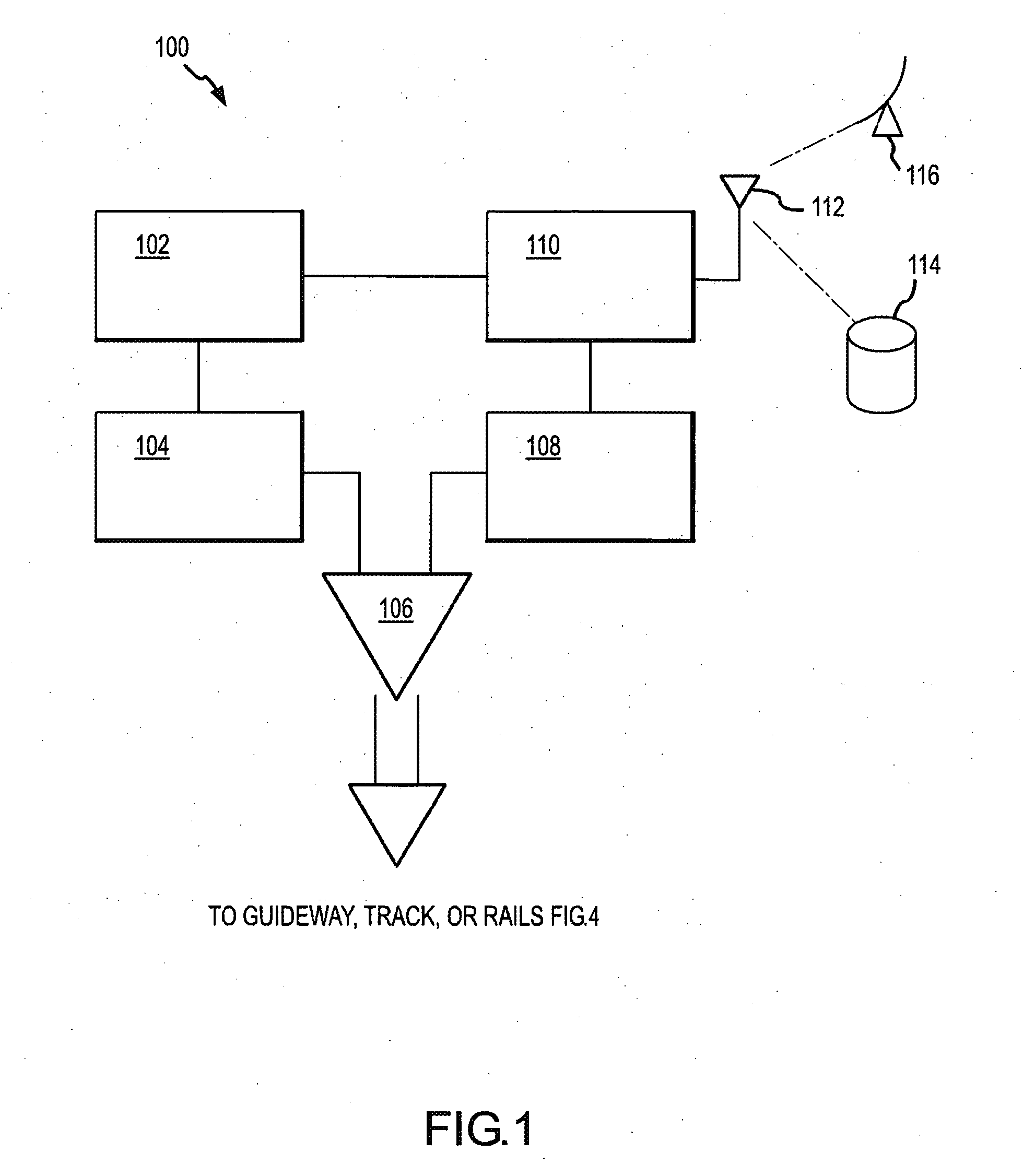
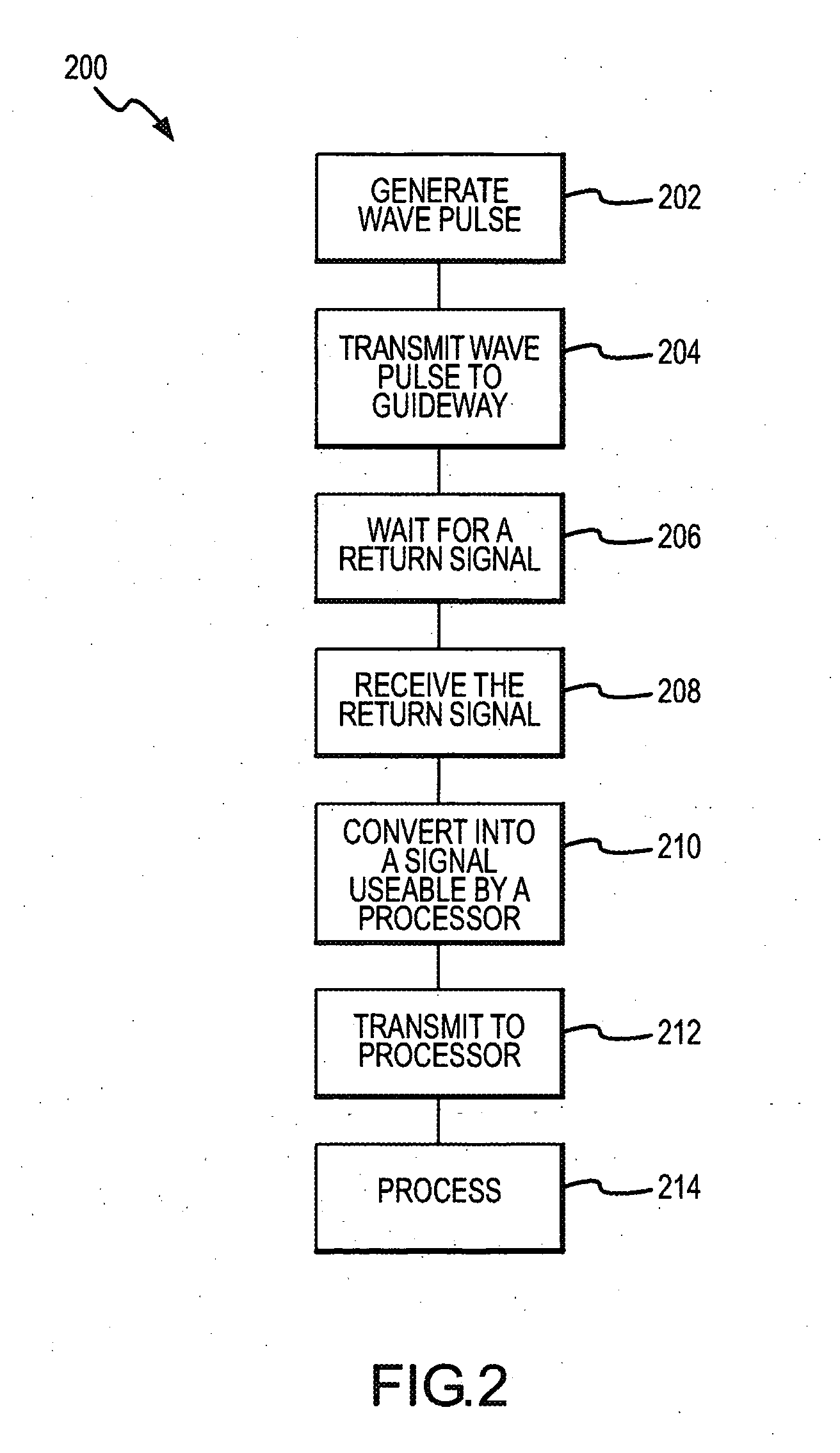
[0019] The present invention will now be described with particular reference to the figure(s). While the present invention is described with particular reference to railroads, locomotives, and the associated tracks, one of ordinary skill in the art will now recognize that the present invention could be used with any system that has a “guideway” where a signal can be transmitted along the guideway. Such guideways include, for example, rail tracks, conveyer belt systems, assembly lines, and other systems where the longitudinal members of the guideways are conductive and at least partially isolated from each other. Alternatively, non-conductive guideways can be made conductive by adding conductors, such as wires or conductive rods.

[0020] The present invention describes an improved rail break detection system operating independently from the existing wayside signaling system. The invention may be used in conjunction with present signaling systems to provide specific advantages such as ...


PUM


Abstract

The present invention provides a method and system for detecting guideway anomalies. In particular, the present invention generates and couples a wave pulse into a guideway. The wave pulse travels down the guideway until it reaches an anomaly. The anomaly causes a return wave pulse. The time difference between the generated wave and the return wave allows calculation of the deference to the anomaly.

Description

[0001] The patent application claims priority to U.S. Provisional Patent Application Ser. No. 60 / 500,385, filed Sep. 5, 2003, titled METHOD AND APPARATUS FOR DETECTING RAIL BREAKS AND OCCUPATION, incorporated herein as if set out in full.FIELD OF THE INVENTION [0002] The present invention relates to track detection systems and, more particularly, to a detection system that detects local and distant rail breaks and track occupation. BACKGROUND OF THE INVENTION [0003] Trains and other rail or guideway moving vehicles and / or objects travel along common tracks at various speeds. The stopping distance of some trains can be many miles, but driver visibility is often less than this distance because of fixed conditions such as curves, embankments, trees, tunnels through hilly or mountainous terrain, and the like, or variable conditions such as poor weather. To maintain the desired operating speeds, train drivers need to know that the track ahead is free of breaks and not occupied by other v...

Claims


Application Information

Patent Timeline
Patent Type & Authority Applications(United States)
IPC IPC(8): B61LB61L21/00B61L23/04
CPCB61L23/041B61L23/047B61L23/044
Inventor TURNER, STEVEN
Owner ANALOGIC ENG
Why Eureka
Try Eureka