Release device and method of manufacturing, installing and operating the same

a technology of release device and release plate, which is applied in the direction of curtain suspension device, curtain accessories, screens, etc., can solve the problems of reducing the span length of the device, reducing the width of the device, and undesirable transverse runners, so as to achieve minimal deflection and high versatility. , the effect of minimal deflection

Inactive Publication Date: 2005-04-14
KONFAB
View PDF24 Cites 33 Cited by
  • Summary
  • Abstract
  • Description
  • Claims
  • Application Information

AI Technical Summary

Benefits of technology

[0006] Embodiments of the present invention provide an apparatus and method which is highly versatile in providing a release device that can be used as a roll release device for short spans and for longer spans (e.g. 25 feet or more as in 60 feet or more spans) with minimal deflection and with a single roll. In addition to providing for minimal deflection, a preferred embodiment of the present invention also provides a roll release device that can be suspended from overhead mounts (e.g. left and right end mounts only) and that can be “tuned” for different roll lengths, curtain weights, etc.

Problems solved by technology

In some uses, as in scenic or stage curtain theatrical use, a transverse runner is undesirable with vertical lifting and dropping being more desirable.
When pulled, the movement of the ropes causes the tube to roll or spin resulting in the tube “climbing” the drop, thereby raising the bottom of the drop.
These devices are limited in span length based on the lack or need for stiffening the tube or pipe.
Physics and typical space and budget constraints have tended to limit these devices often to a width of twenty-four feet or less.
Or devices which require a fixed steel frame which may be utilized only with a fixed, predetermined load and which do not allow for changing the load.
As many areas desired for use with a barrier span larger distances (e.g. 40 to 100 feet), there is introduced the complexity of providing support for these large spans while still providing for efficient roll up and / or down of the barrier.
As the weight of the curtain material alone in the curtains used to cover such spans can be quite high (e.g., 1000 to 1500 lbs or more), as in multiple curtains arranged in series, there is also a need for providing sufficient structural integrity over the spans through the use of high strength materials (with corresponding costs) and extensive or frequent support arrangements along the span such as multiple independent barrier roll assemblies arranged in series, which also increases cost and adds to the roll up complexity.
Architects and contractors know how difficult and expensive it is to build or renovate theaters with standard rigging equipment.

Method used


Image

  • Release device and method of manufacturing, installing and operating the same
  • Release device and method of manufacturing, installing and operating the same
  • Release device and method of manufacturing, installing and operating the same

Examples


Embodiment Construction

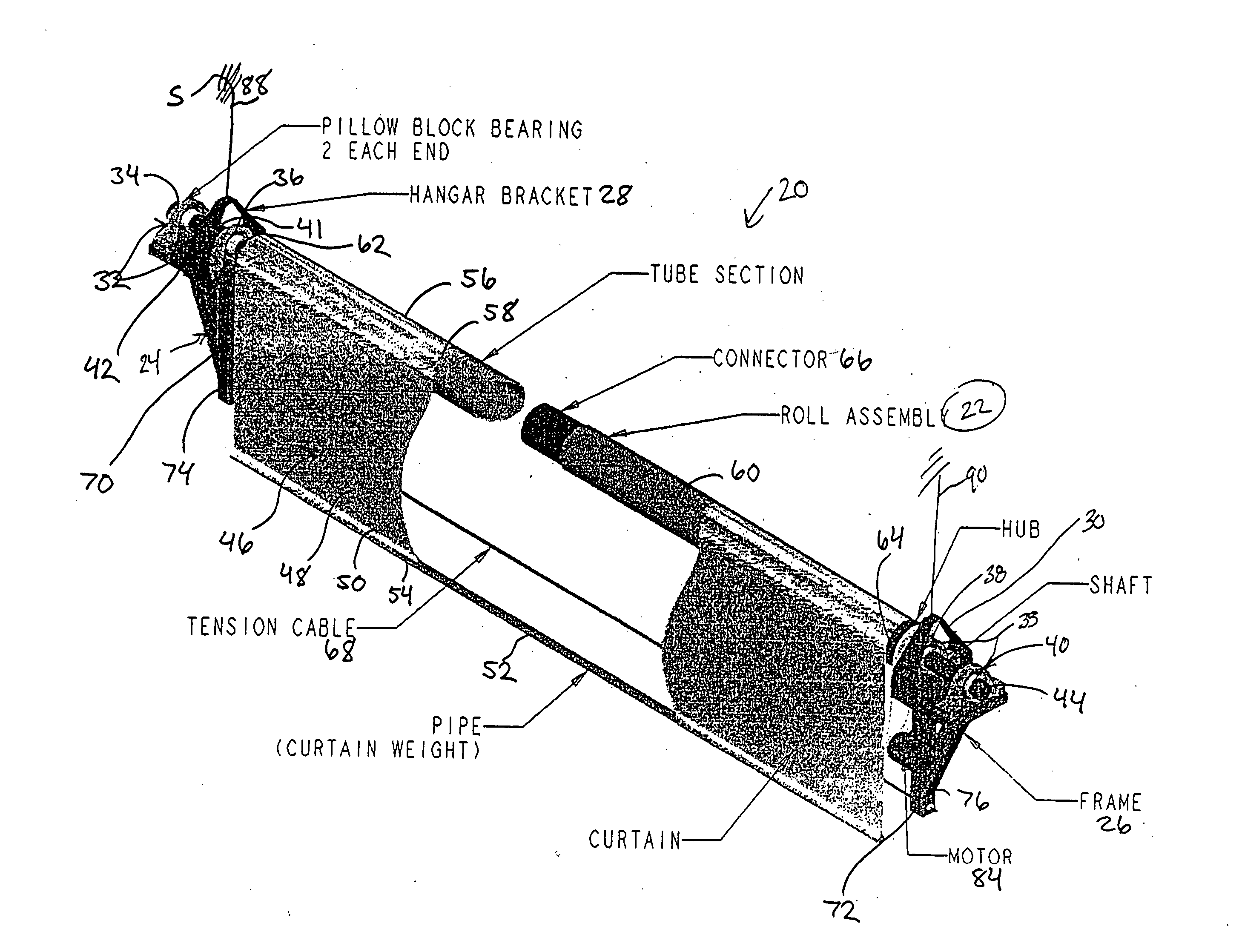
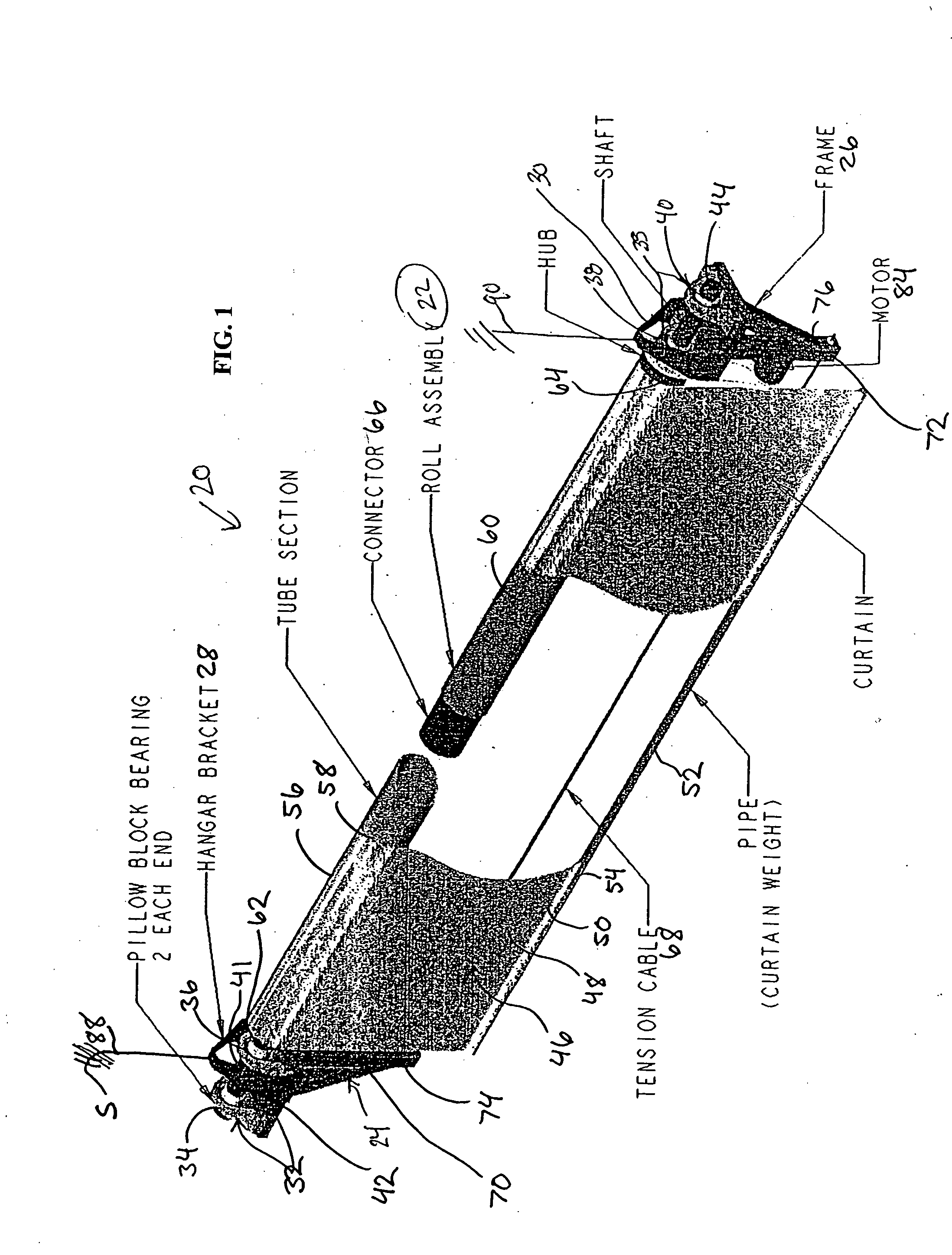
[0036]FIG. 1 illustrates, in perspective, a preferred embodiment of a release device 20 in the form of a roll drop device (hereafter referred to as roll drop device 20) which is well suited for use as a roll drop such as for theatrical banners (e.g., curtains) acoustic banners, sun and environmental control banners, advertising banners, etc. Roll drop device 20 comprises roll assembly 22 which is supported at opposite ends by first frame 24 and second frame 26. First frame 24 is connected with first support connector (e.g., a first hanger bracket assembly) 28, while second frame 26 is connected with second support connector (e.g., a second hanger bracket assembly) 30. As explained in greater detail below, first frame 24 supports bearing assembly 32 (e.g., a bearing set 34, 36) and second frame 26 supports bearing assembly 33 (e.g., a second bearing set 38, 40). The first and second bearing assemblies are shown arranged on the frames to receive the “exposed” shaft ends 42 and 44 of s...


PUM


Abstract

A release device for vertically adjustable barriers (theatrical curtains, advertising banners, sun control systems, environment altering systems, acoustic control systems or scenic back drops, etc.), with a support assembly (e.g., roll assembly) with first and second roll supporting frame structures and a tensioner extending between the frame structures. The tensioner can be a cable extending parallel to the roll's axis of rotation. The tensioner compensates for gravity induced sagging of the roll (e.g., a multi-sectional roll). The frame structures are suspended with suspension lines that extend down from an overhanging mount and the frames compress the ends of the roll and negate sag in intermediate area of roll. The roll is supported by bearing sets on the frame structures.

Description

FIELD OF THE INVENTION [0001] The present invention relates to a release device such as an adjustable barrier roll release device used in supporting flexible (e.g., textile) visual, acoustic and / or environmental blocking barriers such as curtains (e.g., theater), environmental protective barrier sheets (e.g., sun blocks or shades), room dividers, backdrops, netting, advertising banners, etc., and is particularly suited for use with large span roll drop assemblies. BACKGROUND OF THE INVENTION [0002] A variety of flexible barrier or curtain supports have been developed including those designed for handling large spans such as with theatrical curtains or gymnasium dividers and the like. To retract or remove a barrier, particularly one extending over a long span, there has been utilized the technique of transverse sliding of a flexible curtain along an above supported runner with a plurality of carriers each having suspension lines extending down into supporting contact with the curtain...

Claims


Application Information

Patent Timeline
Patent Type & Authority Applications(United States)
IPC IPC(8): A47G5/02A63J1/02E06B9/42
CPCE06B9/42A63J1/02
Inventor RAMSEY, ROBERT M.
Owner KONFAB
Why Eureka
Try Eureka