Weighted pusher

a pusher and weight technology, applied in the field of weighted pushers, can solve the problems of wasting valuable space, unable to meet the requirements of the standard weight-driven pusher, and the structure of the spring-loaded pusher is often complex, so as to maximize the length of the product train and reduce the footprin

Inactive Publication Date: 2005-04-14
DISPLAY TECHNOLOGIES INC
View PDF20 Cites 107 Cited by
  • Summary
  • Abstract
  • Description
  • Claims
  • Application Information

AI Technical Summary

Benefits of technology

The technical effect of this patent is to create a weight-based pusher for displaying products on a store's floor that takes up minimal space and doesn't obstruct other items from being placed on the same shelves. This allows more products to fit into each area, making it easier to stock and organize them efficiently.

Problems solved by technology

The technical problem addressed in this patent is to provide a weight-driven pusher for use on a gravity-fed display shelf that is simple, economical, and suitable for use in a freezer. The pusher should not have a rearwardly extending leg that occupies valuable shelf space and should not require a sled to carry the product. The goal is to maximize the length of the product train and to prevent the pusher from tipping over and becoming ineffective.

Method used


Image

  • Weighted pusher
  • Weighted pusher
  • Weighted pusher

Examples


Embodiment Construction

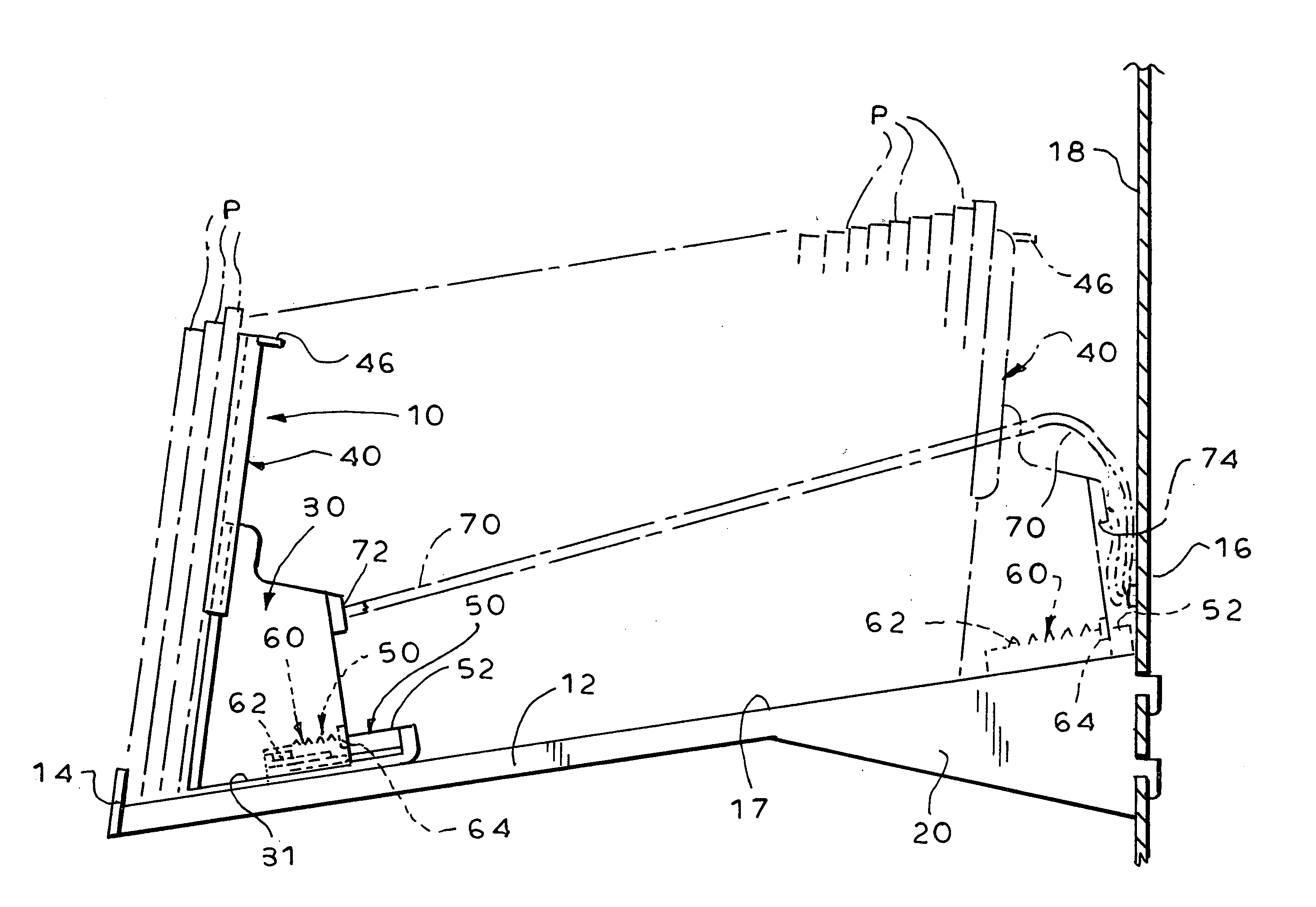
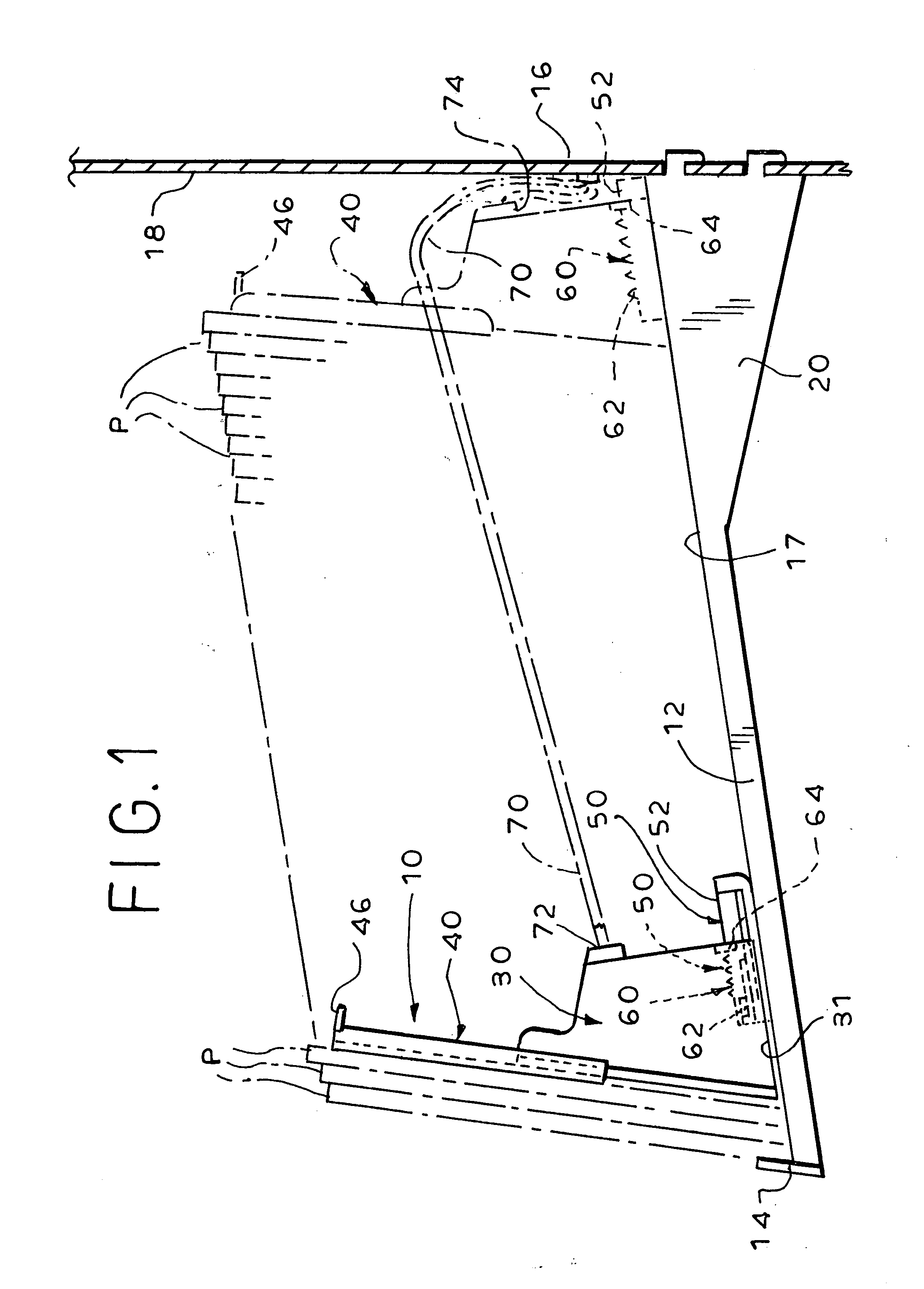
[0017] Referring now to the drawing, and in particular to FIG. 1 thereof, therein illustrated is a weight-driven pusher according to the present invention, generally designated by the reference numeral 10. The pusher 10 rests on a conventional gravity-fed display shelf, generally designated 12, associated with a front stop 14 and a back stop 16. The pusher 10 drives forwardly a product train formed of several items of product P along the floor 17 of the gravity-fed display shelf 12 until the lead product is stopped by the front stop 14 (which may simply be an upstanding ledge at the front of the shelf 12, as illustrated, or any of the more complex stops well known in the display shelf art). The back stop 16 may simply be an upstanding ledge at the back of the shelf 12, whether the back stop 16 is actually part of the shelf 12 or upright 18, or a separate element such as a wall abutting the back of the shelf 12. As is conventional in the art, the shelf 12 is supported in a forward an...


PUM


Abstract

A weight-driven pusher for product on a gravity-fed display shelf includes a weighted frame. A front plate is mounted on the frame and manually adjustable in upper reach relative to the frame to accommodate product of varying height and preclude product from tipping rearwardly over the pusher. A leg assembly is retractably mounted on the frame adjacent the bottom thereof and biased to project rearwardly from the frame to preclude product from tipping the pusher over backwards.

Description


Claims


Application Information

Patent Timeline
Owner DISPLAY TECHNOLOGIES INC
Why Eureka
Try Eureka