Spout assembly for dispensing liquid from a nozzle

a technology of nozzle and nozzle, which is applied in the direction of liquid handling, packaging goods, pliable tubular containers, etc., can solve the problems of fuel leakage or drippage, and achieve the effect of reducing the risk of fuel leakag

Active Publication Date: 2005-04-14
OPW FUELING COMPONENTS LLC
View PDF53 Cites 12 Cited by
  • Summary
  • Abstract
  • Description
  • Claims
  • Application Information

AI Technical Summary

Benefits of technology

[0014] In accordance with further aspects of the invention, a vacuum control mechanism is provided for use in a liquid dispensing nozzle. The vacuum control mechanism includes a fluid conduit adapted for disposition in a spout of a liquid dispensing nozzle. The fluid conduit having a liquid-sensing segment and a nozzle shut-off control segment. The liquid-sensing segment is adapted for disposition at a liquid level sensing location and shut-off control segment is adapted to communicate with a nozzle shut-off mechanism. A check valve is disposed in the fluid conduit and is operative to allow the flow of liquid through the fluid conduit in a direction from the liquid-sensing segment toward the nozzle shut-off control segment and to substantially prevent the flow of liquid in the direction from the nozzle shut-off control segment to the liquid-sensing segment.

Problems solved by technology

In certain applications, such as with delivery of fuel, spout assemblies may have a design that results in undesirable leakage or drippage of fuel that may violate environmental or other regulations.

Method used


Image

  • Spout assembly for dispensing liquid from a nozzle
  • Spout assembly for dispensing liquid from a nozzle
  • Spout assembly for dispensing liquid from a nozzle

Examples


Embodiment Construction

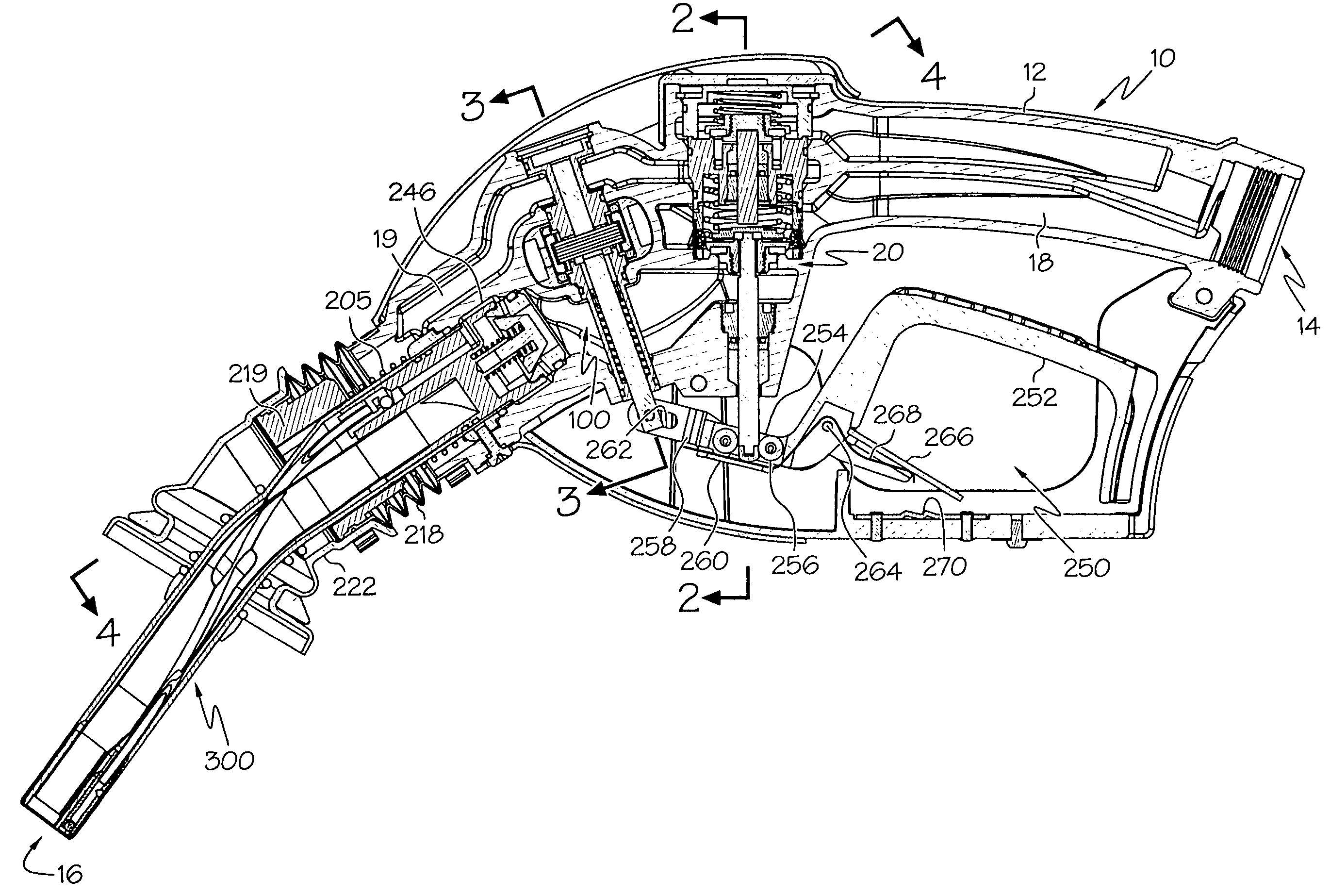
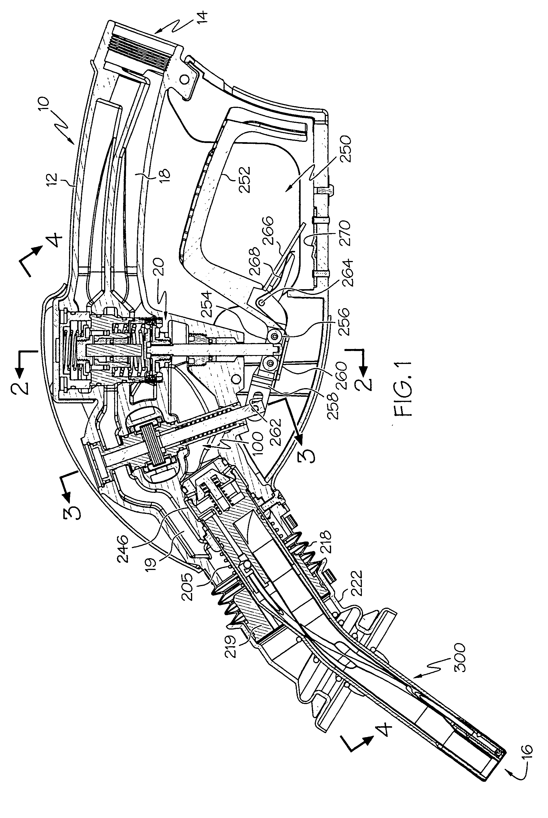
[0051] Turning now to the figures wherein like numbers correspond to similar elements through the views, FIG. 1 depicts a cross sectional view of a nozzle 10 in accordance with one exemplary embodiment of the present invention. Exemplary nozzles described herein may be applied in a wide variety of applications. For example, the nozzles may be used for dispensing liquid from a container. Particular exemplary applications, the nozzle may be used to dispense fuel (e.g., gasoline) from a liquid storage tank.

[0052] As shown in FIG. 1, the nozzle 10 includes a nozzle body 12 with an inlet 14 for receiving liquid. The inlet is designed to be coupled for fluid communication with a liquid storage tank. For example, a flexible hose may be coupled to the inlet 14 to permit fluid communication between a gasoline pump and the nozzle 10 at a gasoline station. In nozzle applications including a vapor recovery arrangement, the inlet 14 may be adapted to couple with a dual function hose, such as a ...


PUM

PropertyMeasurementUnit
internal angleaaaaaaaaaa
obtuse internal angleaaaaaaaaaa
fluid pressureaaaaaaaaaa

Abstract

Spout assemblies are provided for dispensing liquid from a nozzle.

Description

TECHNICAL FIELD [0001] The present invention relates to spout assemblies and more particularly to spout assemblies for dispensing liquid from a nozzle. BACKGROUND OF THE INVENTION [0002] A conventional fluid nozzle includes a spout assembly for dispensing liquid from a nozzle. The spout is attached to the outlet of the nozzle body and the spout assembly includes a discharge end for dispensing fluid. In certain applications, such as with delivery of fuel, spout assemblies may have a design that results in undesirable leakage or drippage of fuel that may violate environmental or other regulations. Consequently, there is a need for spout assemblies for use with a dispensing nozzle that reduces or eliminates leakage or drippage to the surrounding environment. SUMMARY OF THE INVENTION [0003] Accordingly, it is an aspect of the present invention to obviate problems and shortcomings of conventional spout assemblies. More particularly, it is an aspect of the present invention to provide spo...

Claims


Application Information

Patent Timeline
Patent Type & Authority Applications(United States)
IPC IPC(8): B67D7/48B67D7/54
CPCB67D7/48B67D7/52B67D2007/545B67D7/54
Inventor GARRISON, TIMOTHY M.SCHUBERT, HAROLD M.YORK, BRYAN S.PRESTON, DANIEL E.
Owner OPW FUELING COMPONENTS LLC
Why Eureka
Try Eureka