
Temperature/humidity control system for a fuel cell stack and a method thereof

a technology of temperature/humidity control and fuel cell stack, which is applied in the direction of heating types, instruments, applications, etc., can solve the problems of increasing power consumption, requiring separate control logic, and difficult optimization of control logic, so as to reduce the amount of vapor generated by the vibrator

Inactive Publication Date: 2005-04-14
HYUNDAI MOTOR CO LTD
View PDF8 Cites 32 Cited by
  • Summary
  • Abstract
  • Description
  • Claims
  • Application Information

AI Technical Summary

Benefits of technology

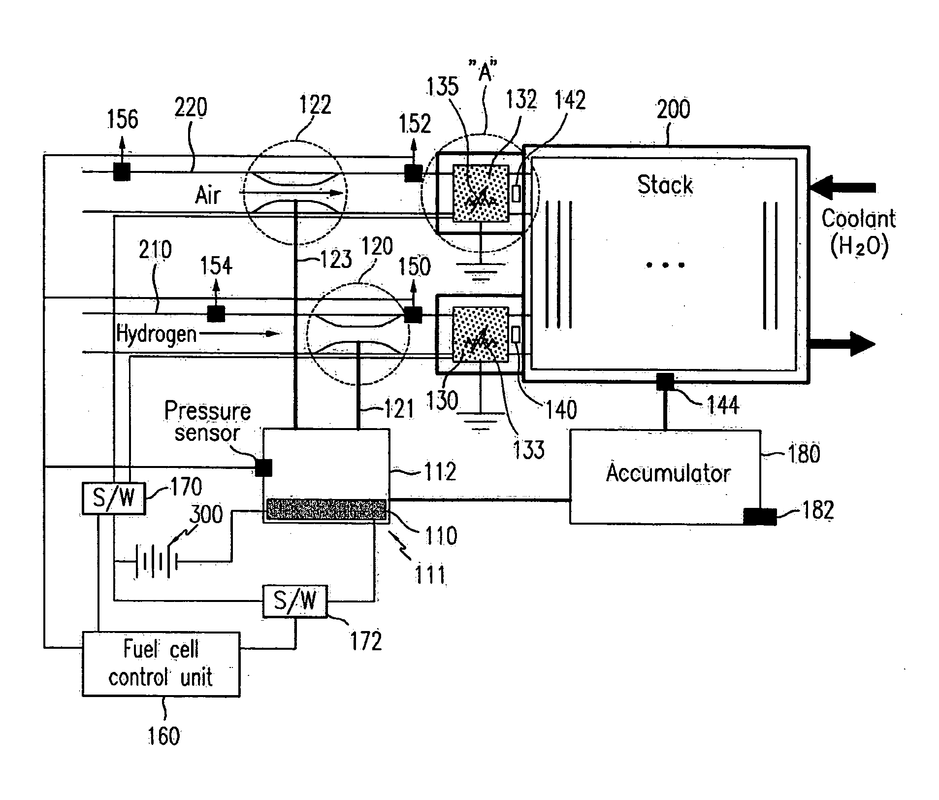
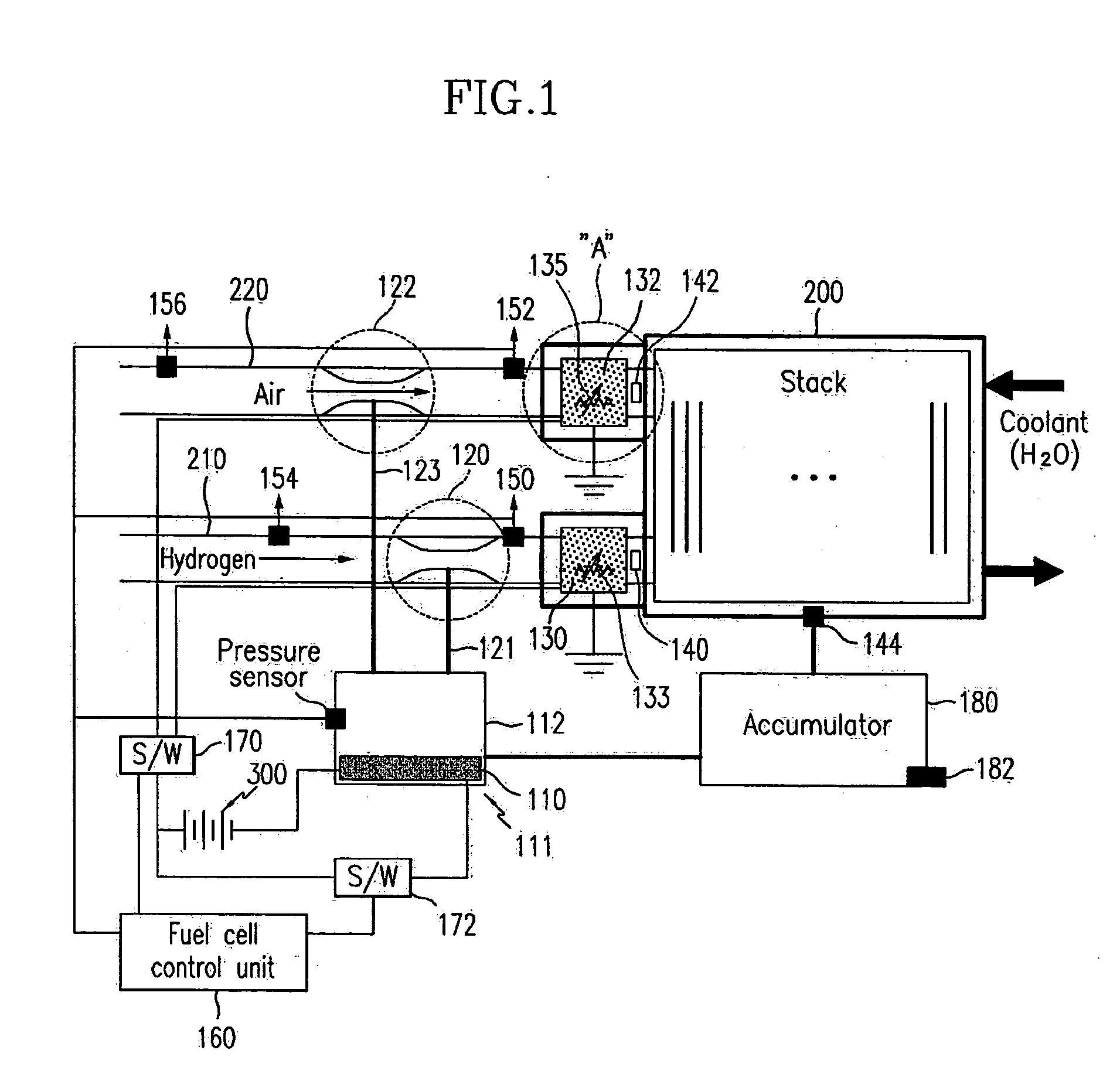
[0012] Embodiments of the present invention provide a temperature / humidity control system for a fuel cell stack in which hydrogen and air supplied to a fuel cell stack can be effectively preheated and humidified.
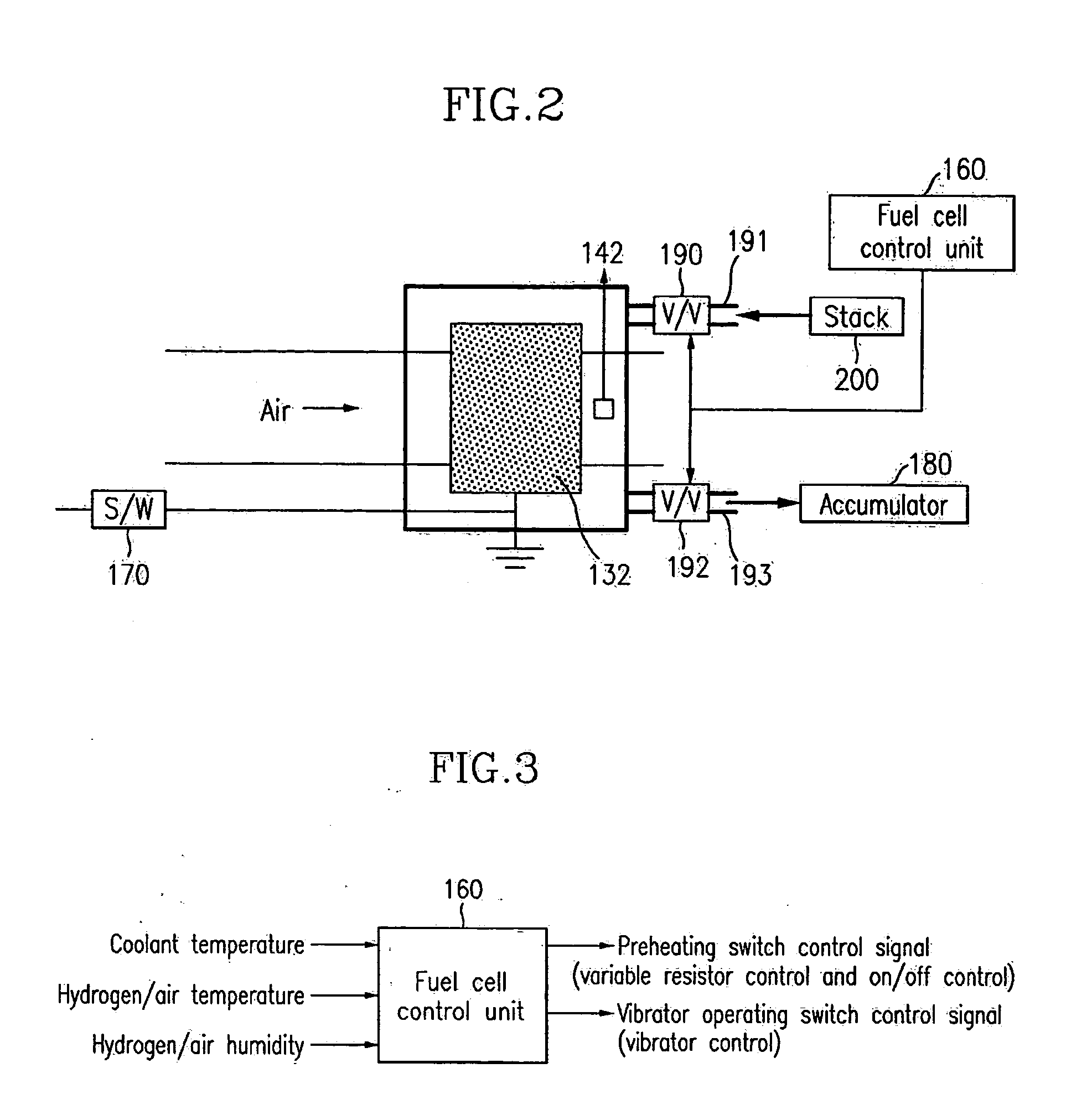
[0030] It is preferable that the fuel cell control unit controls the vibrator such that an amount of vapor generated by the vibrator is decreased if both of the hydrogen humidity detected by the first humidity sensor and the air humidity detected by the second humidity sensor are higher than a second predetermined humidity.
[0039] Preferably, the control method further comprises: detecting a temperature of coolant in the fuel cell stack; and allowing the coolant to circulate in the preheating device to preheat the hydrogen and the air supplied to the fuel cell stack, and simultaneously decreasing the amount of heat generated by the preheating device if the detected coolant temperature is higher than a third predetermined temperature.

Problems solved by technology

This increases power consumption and requires separate control logic.
Therefore, optimization of the control logic becomes very difficult.
Still further, a temperature drop caused by a pressure drop of the hydrogen and caused by the mixing of vapors with hydrogen and air cannot be compensated.

Method used


Image

  • Temperature/humidity control system for a fuel cell stack and a method thereof
  • Temperature/humidity control system for a fuel cell stack and a method thereof
  • Temperature/humidity control system for a fuel cell stack and a method thereof

Examples


Embodiment Construction

[0054] Hereinafter, a preferred embodiment of the present invention will be described in detail with reference to the accompanying drawings.

[0055] The temperature / humidity control system of the fuel cell stack according to the embodiment of the present invention comprises a humidifying device 111 for humidifying hydrogen and air supplied to a fuel cell stack 200, a preheating device for preheating the hydrogen and the air supplied to the fuel cell stack 200, and a fuel cell control unit 160 for controlling the humidifying device 111 and the preheating device.

[0056] The humidifying device 111 comprises a vibrator 110 for converting water into vapor, a storage member 112 configured to store vapor generated by the vibrator 110, and a first mixing member 120 and a second mixing member 122 configured to humidify the hydrogen and the air, respectively, with the vapor stored in the storage member 112. In the first and second mixing members 120 and 122, the vapor is mixed with the hydroge...


PUM

PropertyMeasurementUnit
temperatureaaaaaaaaaa

Abstract

The temperature / humidity control system includes a humidifying device having a vibrator to convert water into vapor. The control system also includes, a storage member storing the vapor generated by the vibrator, and at least one mixing member to humidify hydrogen and air supplied to the fuel cell stack with the vapor stored in the storage member. The control system fuel cell includes a preheating device configured to preheat the hydrogen and air humidified by the mixing member, and at least one temperature sensor detecting temperatures of hydrogen and air having passed the preheating device and a temperature of coolant of the fuel cell stack. Finally, the control system includes at least one humidity sensor detecting humidities of hydrogen and air having passed the humidifying devices, and a fuel cell control unit controlling the humidifying device and the preheating device based on signals of the temperature sensor and the humidity sensor.

Description

CROSS-REFERENCE TO RELATED APPLICATIONS [0001] This application claims priority of Korean Application No. 10-2003-0070620, filed Oct. 10, 2003, the disclosure of which is incorporated fully herein by reference. FIELD OF THE INVENTION [0002] The present invention relates to a temperature / humidity control system for a fuel cell stack, and a control method thereof. BACKGROUND OF THE INVENTION [0003] Generally, in order to generate electric power in a fuel cell stack, hydrogen ions must transfer to a cathode through a membrane. Also, the membrane must be humid for the transferring of the hydrogen ions. [0004] When the hydrogen ions transfer to the cathode, the hydrogen ions take water molecules. Therefore, in order to maintain the humidity of the membrane at an appropriate level, it is needed to humidify hydrogen that is supplied to the fuel cell stack. [0005] There are two general methods for humidifying the hydrogen: one is an internal humidifying method in which humidifying is perfor...

Claims


Application Information

Patent Timeline
Patent Type & Authority Applications(United States)
IPC IPC(8): H01M8/00H01M8/04
CPCH01M8/04029H01M8/04126H01M8/04328H01M8/04358H01M8/045Y02E60/50H01M8/04708H01M8/04768H01M8/04835H01M8/04917H01M8/04507H01M8/04
Inventor HWANG, BYOUNG WOO
Owner HYUNDAI MOTOR CO LTD
Learn More