Apparatus and methods for adjusting the rotational frequency of a scanning device

a scanning device and rotating frequency technology, applied in the direction of recording devices, inking apparatus, instruments, etc., can solve the problems of reducing the print speed, requiring synchronization, and stressing the hinges

Active Publication Date: 2005-04-14
TEXAS INSTR INC
View PDF16 Cites 46 Cited by
  • Summary
  • Abstract
  • Description
  • Claims
  • Application Information

AI Technical Summary

Problems solved by technology

Unfortunately, if the mirror is mounted at a slight angle to compensate for medium movement during the forward beam sweep, the return beam sweeps will traverse a trajectory on the moving photosensitive drum which will be at an angle which is unacceptable with the first printed image line since the effect of the moving medium and the angle mounting of the mirror will now be additive rather than subtractive.
This requirement of only using one of the sweep directions of the mirror of course reduces the print speed and requires synchronization between the mirror and the rotating drum.
For example, the Young's modulus of silicon varies over temperature such that for a MEMS type pivotally oscillating device made of silicon, clamping the device in a package such that it is restrained in the hinge direction will cause stress in the hinges as the temperature changes.
This in turn will lead to drift in the resonant frequency of the pivotal oscillations.
Since applications that use a pattern of light beam scans, such as laser printing and projection imaging require a stable and precise drive to provide the signal frequency and scan velocity, the changes in the resonant frequency and scan velocity of a pivotally oscillating device due to temperature variations can restrict or even preclude the use of the device in laser printers and scan displays.
Further, if the stress loading is increased above the maximum acceptable levels for a given rotational angle, the reliability and operational life of the device can be unacceptably reduced.
For example, excessive compressive stress loading that can occur at low temperature on devices with a CTE (coefficient of thermal expansion) mismatch can lead to buckling of the hinge along with dramatic shift of the resonant frequency or even catastrophic failure.

Method used


Image

  • Apparatus and methods for adjusting the rotational frequency of a scanning device
  • Apparatus and methods for adjusting the rotational frequency of a scanning device
  • Apparatus and methods for adjusting the rotational frequency of a scanning device

Examples


Embodiment Construction

[0033] The making and using of the presently preferred embodiments are discussed in detail below. It should be appreciated, however, that the present invention provides many applicable inventive concepts that can be embodied in a wide variety of specific contexts. The specific embodiments discussed are merely illustrative of specific ways to make and use the invention, and do not limit the scope of the invention.

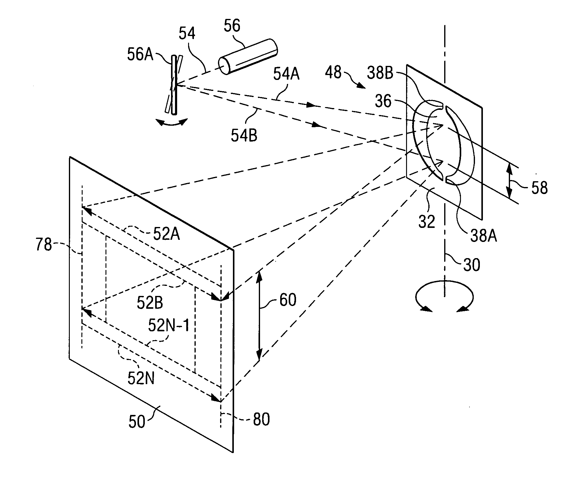
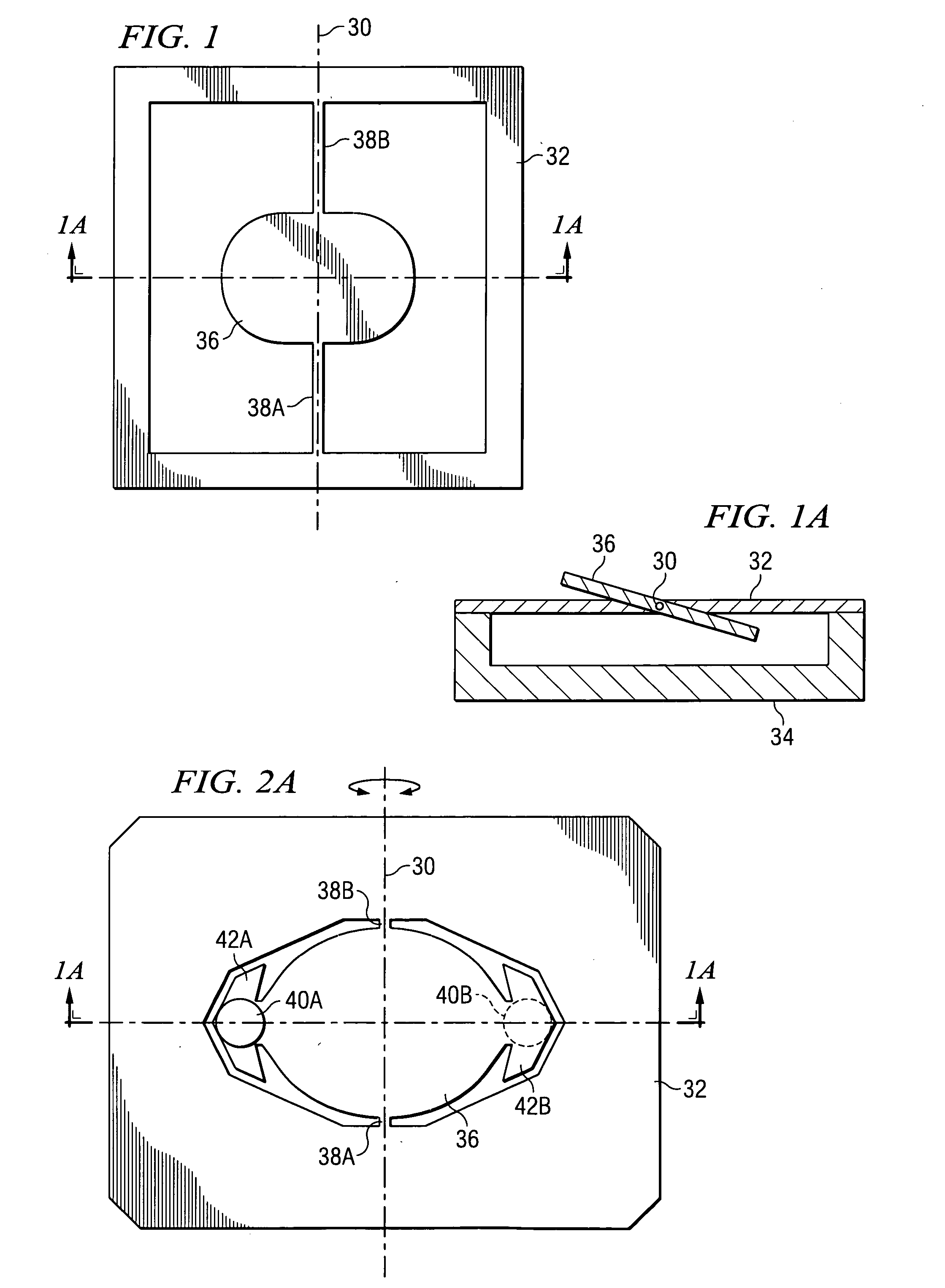
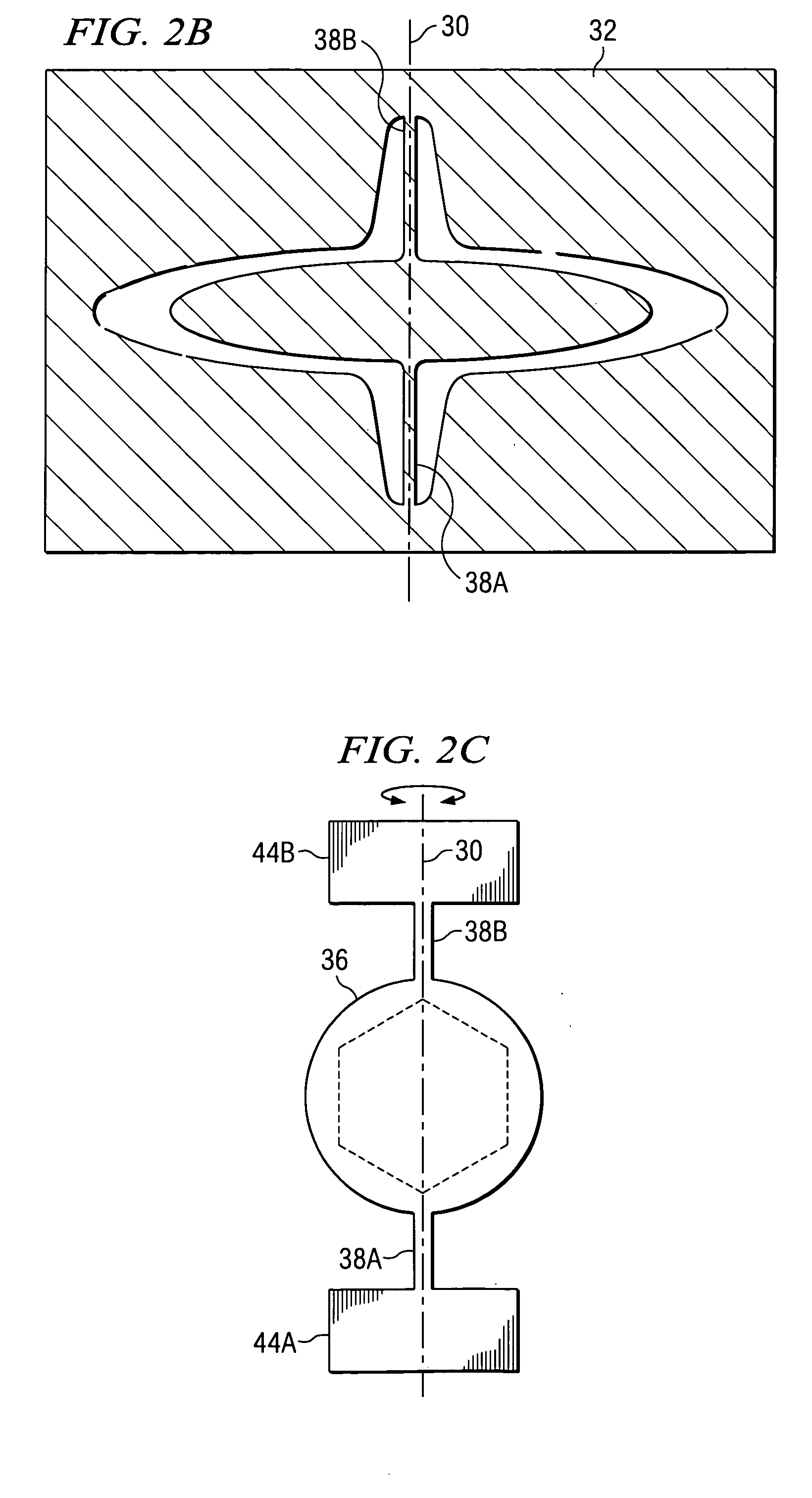
[0034] Like reference numbers in the figures are used herein to designate like elements throughout the various views of the present invention. The figures are not intended to be drawn to scale and in some instances, for illustrative purposes, the drawings may intentionally not be to scale. One of ordinary skill in the art will appreciate the many possible applications and variations of the present invention based on the following examples of possible embodiments of the present invention. The present invention relates to a torsional hinged structure or apparatus with a movea...


PUM


Abstract

The present invention provides methods and apparatus for adjusting the resonant frequency, scan velocity or other parameters of a pivotally functional surface such as an oscillating mirror used as the scanning engine of a laser printer or projection display. The selected parameter is adjusted by the application of tensional or compression stress to the torsional hinges of the mirror. According to one embodiment, the appropriate stress is generated by a slice of piezoelectric material bonded to the mirror device itself or to other portions of the support structure of the scanning engine.

Description

TECHNICAL FIELD [0001] The present invention relates generally to the field of torsional hinge MEMS scanning engines, and more particularly to methods and apparatus for reducing or eliminating variations in the resonant frequency and / or scan velocity of the beam scan caused by environmental factors such as temperature. BACKGROUND [0002] The use of rotating polygon scanning mirrors in laser printers to provide a beam sweep or scan of the image of a modulated light source across a photoresistive medium, such as a rotating drum, is well-known. In addition, there have also been efforts to use a much less expensive flat mirror with a single reflective surface, such as a mirror oscillating in resonance to provide the scanning beam. Earlier efforts to use the inexpensive flat mirror required a compromise in performance in that only one direction of the resonant beam sweep could be used to display or print an image line at a right angle on a page. For example, to generate image lines that a...

Claims


Application Information

Patent Timeline
Patent Type & Authority Applications(United States)
IPC IPC(8): B41J2/47G02B26/08G02B26/10
CPCB41J2/471G02B26/101G02B26/0833
Inventor TUMER, ARTHUR MONROE
Owner TEXAS INSTR INC
Why Eureka
Try Eureka