Method and apparatus for compensating for disc eccentricity in optical disc servo system
- Summary
- Abstract
- Description
- Claims
- Application Information
AI Technical Summary
Benefits of technology
Problems solved by technology
Method used
Image

Examples
Embodiment Construction
[0025] Reference will now be made in detail to the embodiments of the present invention, examples of which are illustrated in the accompanying drawings, wherein like reference numerals refer to the like elements throughout. The embodiments are described below to explain the present invention by referring to the figures.
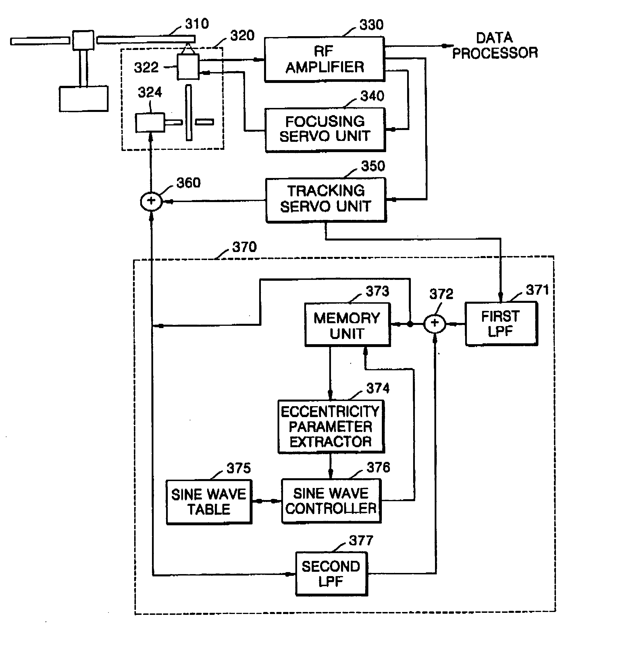
[0026]FIG. 3 is a block diagram of an optical disc driving apparatus having an eccentricity compensation function according to the present invention.
[0027] First, an RF amplifying unit 330 amplifies an RF signal read by a pickup 320 and detects a tracking error signal and a focusing error signal from the amplified RF signal.
[0028] A focusing servo unit 340 receives the focusing error signal detected by the RF amplifying unit 330 and generates a focusing servo control signal. A tracking servo unit 350 receives the tracking error signal detected by the RF amplifying unit 330 and generates a tracking servo control signal. A focus actuator 322 in the pickup 320 causes ...
PUM
 Abstract
Description
Claims
Application Information