Fastening tool and fastening bolt

a technology of fastening tool and fastening bolt, which is applied in the direction of washers, rod connections, screws, etc., can solve the problems of prone to loosening of the fastened portion, and insufficient fastening force of the fastening bolt, etc., to achieve convenient fixing to each other, large displacement load, and sufficient fastening for

Active Publication Date: 2005-04-14
ISEL CO LTD
View PDF9 Cites 13 Cited by
  • Summary
  • Abstract
  • Description
  • Claims
  • Application Information

AI Technical Summary

Benefits of technology

[0023] According to the fastening tool of the present invention, since the displacement load at the time of fastening of the bolt applied to the seat surface of the bolt through hole in the fastening body is largely moderated, the strength of the one end having the bolt through hole of the fastening bolt is enhanced, and the end surface of the slot groove is prevented from swelling and as a result, the fastening force can sufficiently be secured.
[0024] According to the fastening bolt of the present invention, even if the threaded hole of the member into which the fastening bolt is to be threadedly inserted is inclined or the fastening bolt itself is bent, a large displacement load is not applied to the seat surface and the fastening bolt, and the first member and the second member can easily be fixed to each other. The loosening preventing effect is reliably exhibited, and the strong fastening force can reliably be exhibited between the two members.

Problems solved by technology

Therefore, there is a problem that the fastening force of the fastening bolt 501 is insufficient and the fastened portion is prone to get loose.
In such a case also, there is a problem that the fastening force of the fastening bolt 501 becomes insufficient, and the fastened portion is prone to get loose.
When two slot grooves are provided at two portions and the fastening body is divided into two pieces and two fastening bolts 501 are used to fasten (FIG. 1 of Japanese Patent Application Laid-open No.2001-295851), it is practically difficult to uniformly fasten the fastening bolts 501, and the same problem is generated.

Method used


Image

  • Fastening tool and fastening bolt
  • Fastening tool and fastening bolt
  • Fastening tool and fastening bolt

Examples


example

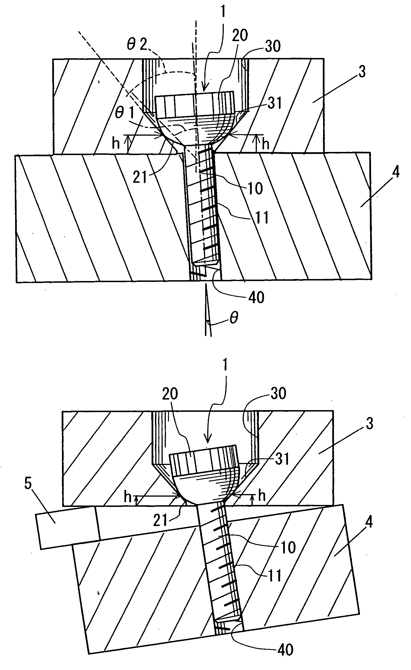
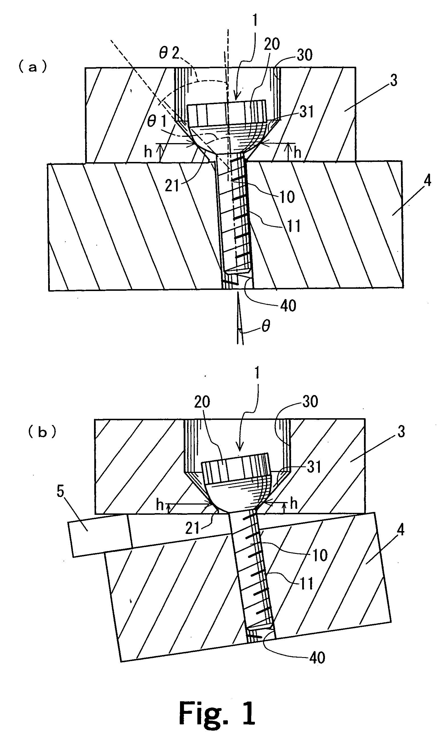
[0074] The lower surface of the head of the bolt of the embodiment 1 to 3 used the fastening bolt (fastening bolt 1 in FIG. 1(a)) formed on the tapered curved surface, and the lower surface of the head of embodiments 4 to 6 used the fastening bolt (fastening bolt 1a in FIG. 4) formed on merely a tapered surface, and the transmission torque when the fastening bodies sandwiching the shaft by the fastening bolt were fastened was measured. The fastening bolt is fastened with a predetermined fastening torque and then, the shaft is fixed so that the shaft does not rotate, and a load is applied to the fastening body in the rotation direction. In this state, a torque value when the fastening body starts rotating is the transmission torque.

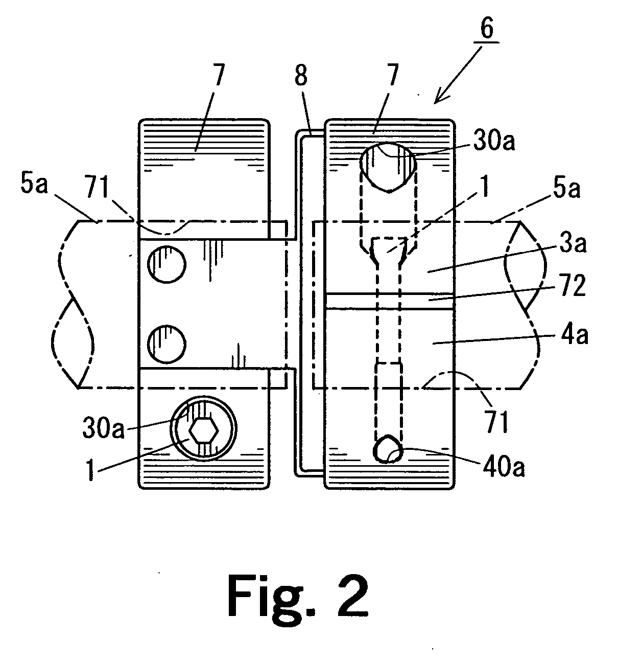
[0075] In the embodiments 1 and 4, a fastening bolt whose head is of M5 size (diameter of the head is 8.5 mm) was used, and a C-ring fastening body 7 shown in FIG. 3(a) was used as the fastening body.

[0076] In the embodiments 2 and 5, a fastening bolt wh...


PUM


Abstract

The present invention provides a fastening tool in which even when two members are inclined as the members are threadedly inserted, a displacement load is not applied to the members almost at all. A fastening bolt 1 of the fastening tool includes a rod-like bolt body 10 provided at its outer periphery with a male thread 11, and a head 20 provided on an end of the bolt body 10 and having a diameter greater than that of the bolt body 10. A lower surface of the head 20 is a tapered surface whose diameter is reduced toward the bolt body 10 so that the lower surface abuts against a tapered seat surface 31 of the first member 3 provided with a bolt through hole 31. This tapered surface is formed into a tapered curved surface 21 finished into a curved surface. With this structure, even if the threaded hole 40 of the second member 4 into which the fastening bolt 1 is threadedly inserted is inclined, the tapered curved surface 21 appropriately slides on the tapered seat surface 31 in the first member 3, the threadedly insertion direction of the bolt body 10 substantially matches with the axial direction of the threaded hole 40. Therefore, the fastening bolt 1 can easily enter concentrically with the threaded hole 40.

Description

BACKGROUND OF THE INVENTION [0001] 1. Field of the Invention [0002] The present invention relates to a fastening tool and a fastening bolt for fixing two members without applying a large displacement load to the fastening bolt or a seat surface of the member. [0003] 2. Disclosure of the Prior Art [0004] Conventionally, a fastening bolt comprises a rod-like bolt body having a male thread, and a head provided on an end of the bolt body, and the fastening bolt is used in various mechanical elements. A bolt body of the fastening bolt is inserted into a bolt through hole formed in a first member, the bolt body is threadedly engaged with a threaded hole formed in a second member, thereby fixing these two members to each other. [0005] The fastening bolt is used for a shaft coupling as a fastening tool as shown in FIG. 8(a). [0006] In this case, a fastening bolt 501 is used for fastening a fastening body 507 for fixing two shafts 505 in a shaft coupling which connects the two shafts 505 to ...

Claims


Application Information

Patent Timeline
Patent Type & Authority Applications(United States)
IPC IPC(8): F16B39/28F16B5/02F16B35/06F16L21/06
CPCF16B5/025F16B35/06F16L21/065Y10T403/535Y10T24/1441Y10T403/53Y10T403/5786Y10T403/75Y10T403/5761F16B39/28
Inventor MOCHIZUKI, KENJI
Owner ISEL CO LTD
Why Eureka
Try Eureka