Tensioner lever

Inactive Publication Date: 2005-04-14
TSUBAKIMOTO CHAIN CO
View PDF6 Cites 11 Cited by
  • Summary
  • Abstract
  • Description
  • Claims
  • Application Information

AI Technical Summary

Benefits of technology

[0008] The transmission medium, which approaches the pivot end of the lever, is sufficiently guided and controlled on the curved guide region of the lever, and it is not necessary to depend on the portion of the lever near its tip for guiding and controlling the approaching portion of the transmission medium. Accordingly, the tensioner lever according to the invention can be freely designed to adapt to changes in sliding resistance, in tension, and in the line of travel, which are apt to occur in the tr

Problems solved by technology

With the conventional tensioner lever, problems are frequently encountered in designing the layout of the path of travel of the transmission chain, especially in the case where the tensioner lever is intended for use in various different engines.
More specifically, since the shoe of a conventional tensioner lever has a long abutment region, the distance between the shafts of the driving sprocket and the driven sprocket is necessarily long.
Moreover, the lengths of the spans o

Method used


Image

  • Tensioner lever
  • Tensioner lever
  • Tensioner lever

Examples


Example

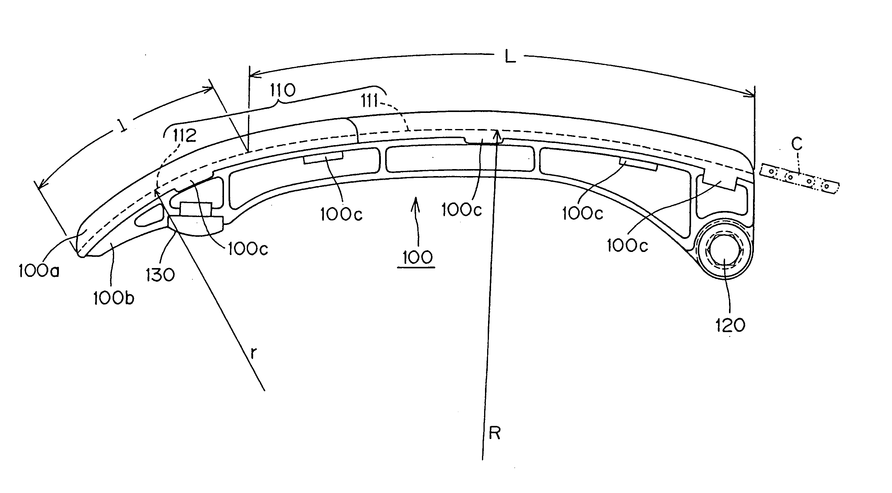
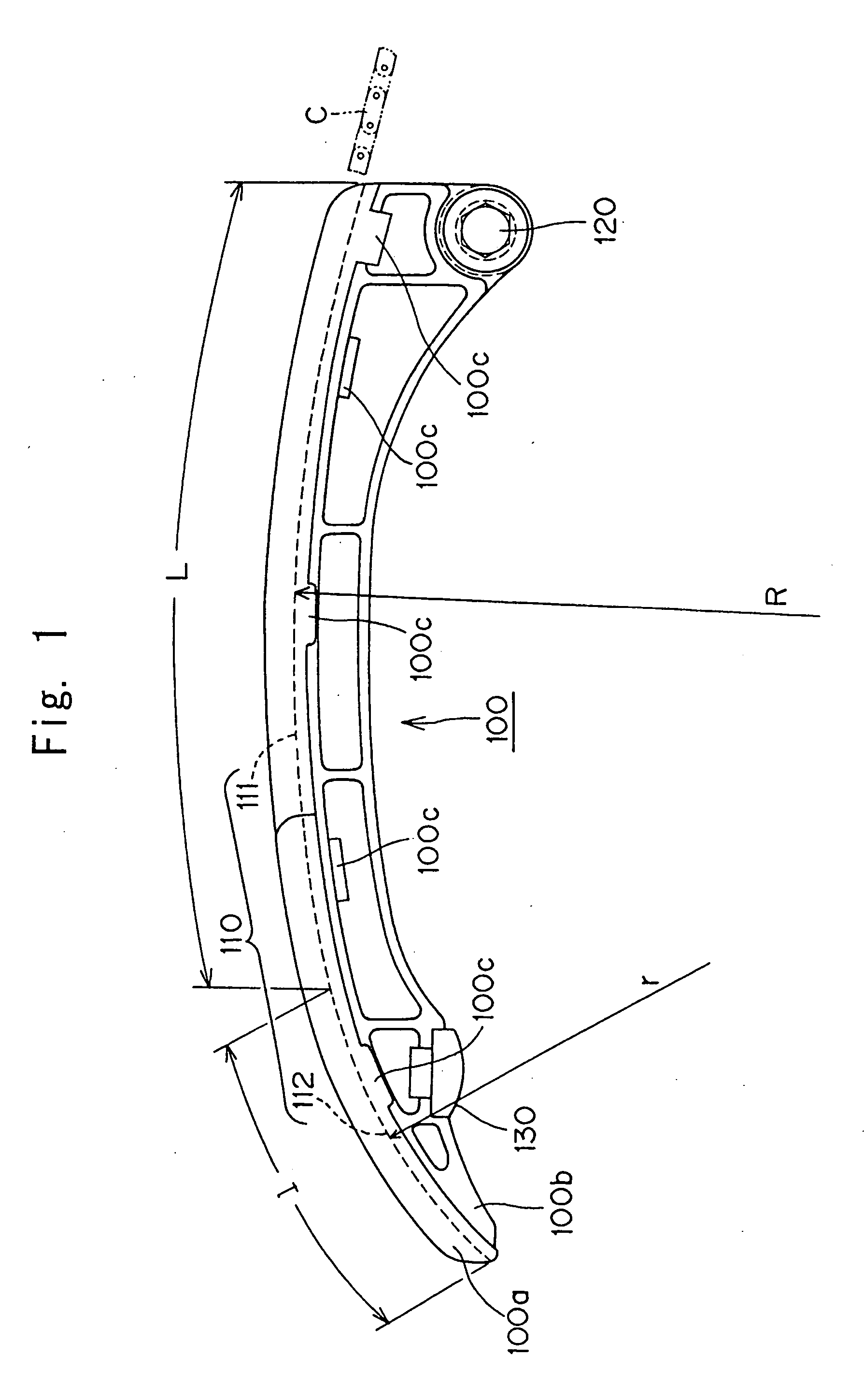
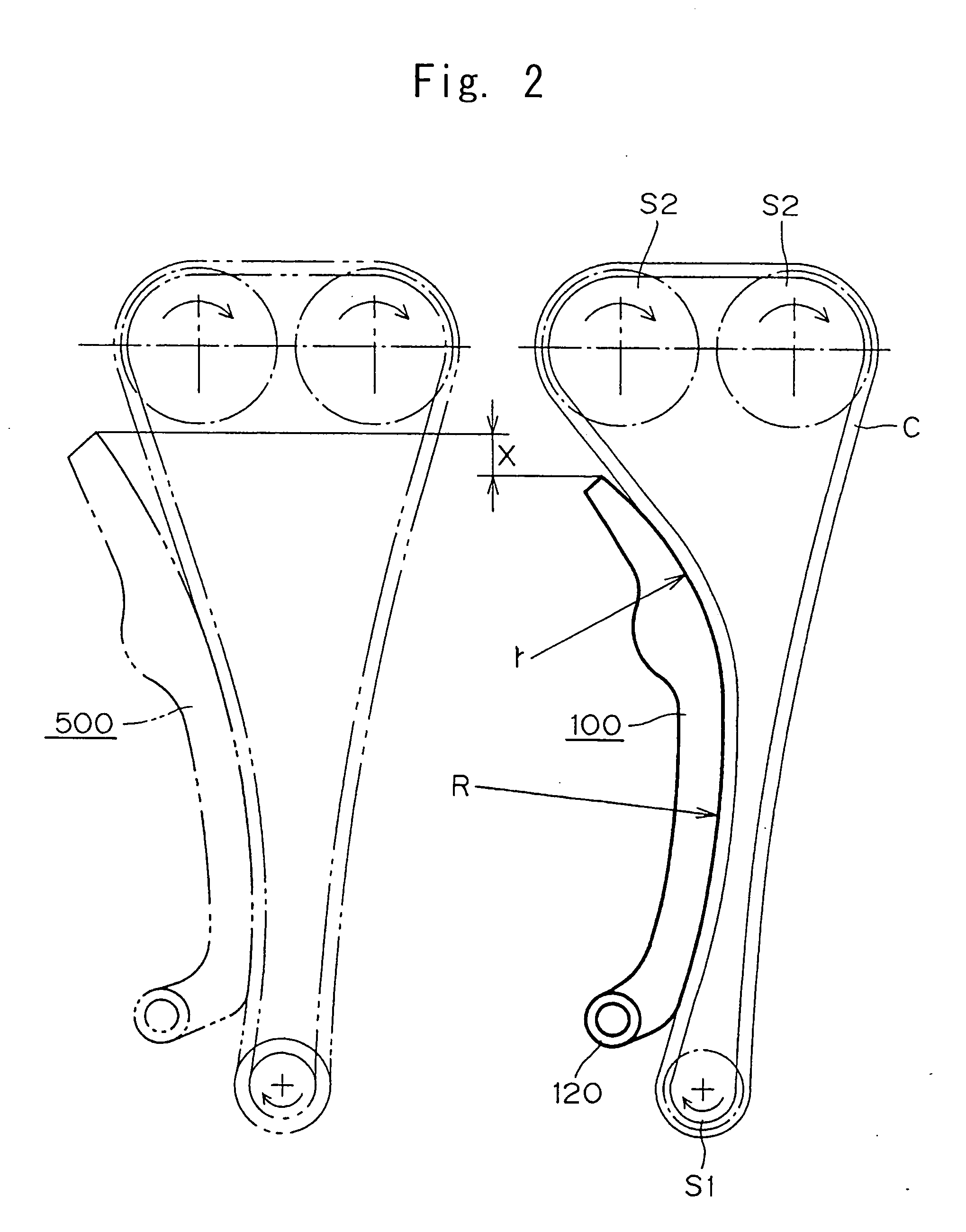
[0014] The tensioner lever in accordance with the invention maintains the required tension in an endless, flexible transmission medium which travels around a driving sprocket and one or more driven sprockets, The lever is pivoted on an axis adjacent the end approached by the transmission medium as it travels away from the driving sprocket. In the lever, an arc-shaped shoe surface is in sliding contact with the endless, flexible, transmission medium. The curved shoe surface comprises two regions. The first region is a curved guide surface region, which guides and controls the approaching transmission medium. The second region is a curved pressing surface region, continuous with the guide surface region, for absorbing slack in the portion of the transmission medium between the tip of the lever and the driven sprocket.

[0015] Except for the fact that the shoe surface is arc-shsped, the structure of the tensioner lever can take any of a broad variety of forms. For example, the lever can...


PUM


Abstract

In a pivoted tensioner lever for maintaining tension in an automobile engine timing chain, an arc-shaped shoe on which the timing chain slides, comprises a guide region, which guides and controls the part of the transmission chain approaching the end of the lever near the pivot axis, and a pressing region, which is continuous with the guide region, and which absorbs the looseness of the transmission chain moving away from the tip of the lever. The radius of curvature of the pressing region is smaller than the radius of curvature of the pressing region.

Description

FIELD OF THE INVENTION [0001] This invention relates to a tensioner lever of the type used in the timing transmission of an automobile engine, or in a similar machine where power is transmitted by an endless, flexible, transmission medium, such as a roller chain or a silent chain, from a driving sprocket to one or more driven sprockets. BACKGROUND OF THE INVENTION [0002] An example of a typical tensioner lever is described and shown in Japanese Patent No. 3448122 (on page 1, and FIGS. 1 to 4). The purpose of the tensioner lever is to preventing transmission failure due to excessive tension or excessive looseness of the transmission chain. The lever comprises an arm, pivotable about a pivot axis adjacent one end of the lever, and a shoe extending lengthwise along the arm, from one end of the arm to the other [0003] In the conventional tensioner lever, the curvature of the chain-engaging surface of the shoe is uniform. That is, it has a constant radius of curvature. With the conventio...

Claims


Application Information

Patent Timeline
IPC IPC(8): F16H7/08F16H7/18
CPCF16H2007/0872F16H7/08
Inventor HASHIMOTO, HIROSHIMORI, KAORI
Owner TSUBAKIMOTO CHAIN CO
Why Eureka
Try Eureka