Locking nail and stereotaxic apparatus therefor

a technology of stereotaxic apparatus and locking nail, which is applied in the field of stereotaxic apparatus for locking nail, can solve the problems of reducing the accuracy of positioning, requiring a comparatively expensive stereotaxic apparatus to orient the drill, and inability to take into account any warp or distortion of the locking nail that occurs, etc., and achieves the effect of increasing the accuracy of positioning

Inactive Publication Date: 2005-04-14
STRYKER EURO OPERATIONS HLDG LLC
View PDF50 Cites 44 Cited by
  • Summary
  • Abstract
  • Description
  • Claims
  • Application Information

AI Technical Summary

Benefits of technology

[0009] It is one aspect of the present invention to provide a stereotaxic apparatus for a locking nail which allows detection of the position of the cross-bore in the locking nail as exactly and reliably as possible by simple means.
[0010] The inventive stereotaxic apparatus is designed to orient a guide sleeve to place a drill and / or bone screw relative to a cross-bore of an inserted locking nail. For this purpose, the locking nail has two oscillating circuits which are arranged along the longitudinal direction of the locking nail. When the stereotaxic apparatus is in an oriented condition the central axis of the guide sleeve essentially coincides with the central axis of the cross-bore. The stereotaxic apparatus has three or more oscillating circuits in a first plane that are equidistant each from a first center located in said plane. Three or more oscillating circuits are also arranged in a second plane extending in parallel with said first plane and are equidistant each from a second center located in said second plane. The first and second planes are arranged towards each other such that a face normal to one of the planes extends through the first and second centers. Additionally, a pair of oscillating circuits are provided spaced from the straight line extending through said centers, the interconnecting straight line of the oscillating circuits, in the condition aligned with the locking nail of the stereotaxic apparatus, is substantially perpendicular to the longitudinal direction of the locking nail. The first plane serves from positioning in an xy plane. For a better survey, the axis of the cross-bore extends in a z direction, and the longitudinal direction of the locking nail in the x direction. Needless to say that the inventive stereotaxic apparatus can also be employed if the longitudinal direction of the locking nail and the axis of the cross-bore are not orthogonal to each other. With this geometry, the first plane including the oscillating circuits defines the position of the stereotaxic apparatus in the xy plane. To discover the correct position, a search is made of that position of the stereotaxic apparatus in which the oscillating circuits in the first plane receive an electromagnetic field of an oscillating circuit in the locking nail at the same intensity. Once the position is fixed in the xy plane it has to be made sure that the axis of the guide sleeve or stereotaxic apparatus is prevented from tilting with respect to the z axis of the cross-bore. The purpose is served by the second plane arranged in parallel with the first plane with its oscillating circuits. If signals of the same intensity are also detected by these oscillating circuits it is sure that the axes of the guide sleeve and cross-bore coincide. However, it is still possible to rotate the stereotaxic apparatus about this axis. To fix this degree of freedom as well, the additional pair of oscillating circuits helps in measuring the signal of a second oscillating circuit from the locking nail. To this end, the additional pair of oscillating circuits is oriented to be perpendicular to the longitudinal direction of the locking nail. If the two oscillating circuits receive signals of an equal intensity the stereotaxic apparatus has been oriented completely in a precisely defined position to the bone nail and the position of the cross-bores can be determined relative to this reference position. The oscillating circuits provided in the locking nail and stereotaxic apparatus are preferably operated at their resonant frequency.
[0011] In a preferred aspect, four oscillating circuits are arranged in a rectangle towards each other in the first and / or second plane. It is preferred to choose a square as the rectangle. The rectangular arrangement of the receiving oscillating circuits in the planes of the stereotaxic apparatus appreciably increases the accuracy in positioning.

Problems solved by technology

The drawback of this device is that it is impossible to take into account any warp or distortion of the locking nail that occurs while it is being driven in.
However, a drawback of a locking nail configured in this way is that since only a single oscillating circuit is used a comparatively expensive stereotaxic apparatus is required to orient the drill.
Further, it proves a disadvantage that the oscillating circuit is arranged just in the channel of the cross-bore and has to be removed after the stereotaxic apparatus is oriented.

Method used


Image

  • Locking nail and stereotaxic apparatus therefor
  • Locking nail and stereotaxic apparatus therefor
  • Locking nail and stereotaxic apparatus therefor

Examples


Embodiment Construction

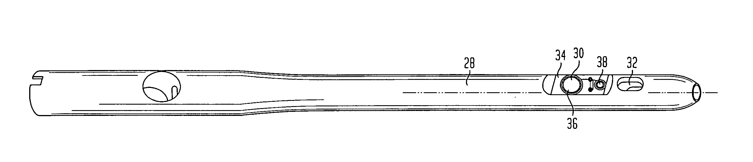
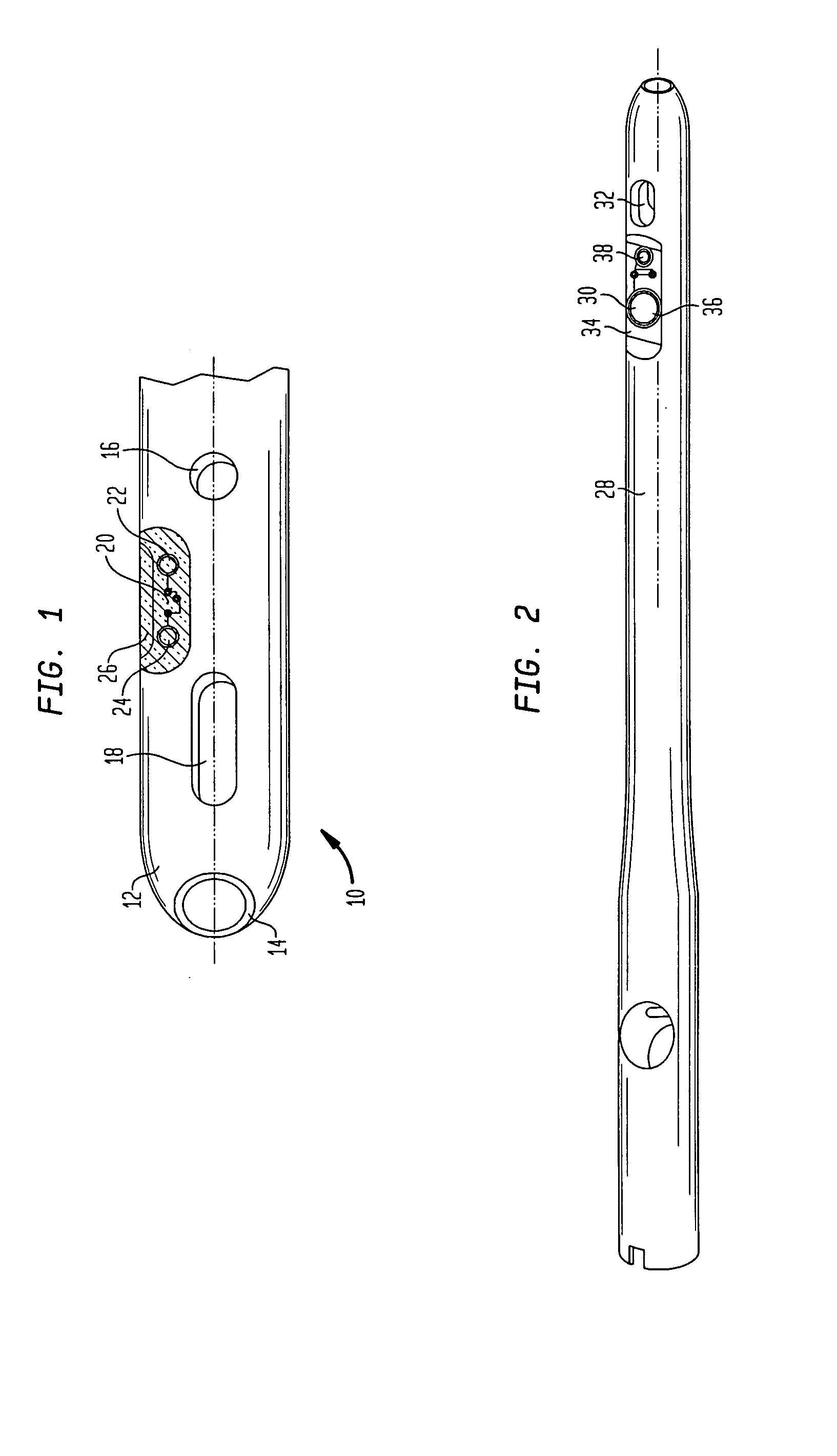
[0026]FIG. 1 shows the top of a preferred locking nail 10 which has a hollow or cannulated shank 12 with an opening in the tip 14. Two cross-bores 16 and 18 are provided in the shank 12. The cross-bore 18 is designed as an elongate hole in the embodiment shown. In the shank wall, a recess 20 is countersunk into the shank wall in the area between the cross-bores 16 and 18. Two schematically shown oscillating circuits 22 and 24 are provided in the recess 20. The oscillating circuits have a coil and a capacitor each of which are electrically tuned to each other. In the embodiment shown, the oscillating circuits are interconnected electrically. However, it is also imaginable to provide two electrically independent oscillating circuits. For an excitation of the oscillating circuits, the stereotaxic apparatus generates a short high-frequency pulse (HF pulse). The frequency of the pulse corresponds to the resonant frequency of the oscillating circuit requiring excitation in the nail or is ...


PUM


Abstract

A stereotaxic apparatus for a locking nail which has two oscillating circuits which are disposed along the longitudinal direction of the locking nail. The apparatus has a guide sleeve to place a drill and/or bone screw which, when the stereotaxic apparatus is in an oriented condition, points to a cross-bore in the locking nail. The guide sleeve has three or more oscillating circuits arranged in a first plane that are equidistant each from a first center located in the plane; three or more oscillating circuits are arranged in a second plane extending in parallel with said first plane that are equidistant each from a second center located in said second plane. The first and second planes are arranged towards each other such that a face normal to one of said planes extends through the first and second centers. A pair of oscillating circuits are arranged at a distance from a straight line extending through the centers and the interconnecting straight line of which, in the aligned condition with the locking nail, is substantially perpendicular to the longitudinal direction of the locking nail.

Description

BACKGROUND OF THE INVENTION [0001] The present invention relates to a stereotaxic apparatus for a locking nail which has two oscillating circuits arranged along its longitudinal direction. The invention also relates to the locking nail. [0002] Locking nails which can be introduced in the shin and thigh bones mostly have several cross-bores through which bone screws are passed to hold the locking nail safely in the bone channel. A particular difficulty in doing so is to locate the cross-bore in the implanted nail. The purpose is served by stereotaxic apparatus. In a category of stereotaxic apparatus, the bone is radiographed by X-rays and the cross-bores of the locking nail in the bone are visualized on a monitor. Additionally, a target element is illustrated in the X-ray image so that a marking lying on the axis of the cross-bore can be made at the outside of the bone. [0003] In another category of stereotaxic apparatus, the apparatus is fixedly joined to the implantable nail. A bra...

Claims


Application Information

Patent Timeline
Patent Type & Authority Applications(United States)
IPC IPC(8): A61B17/56A61B17/17A61B17/72
CPCA61B17/1707A61B2019/547A61B17/72A61B17/1725A61B2090/397
Inventor SIMON, BERNDFULLGRAF, RENE
Owner STRYKER EURO OPERATIONS HLDG LLC
Why Eureka
Try Eureka