
Knee extension apparatus

Inactive Publication Date: 2005-04-14
DOCTORS ORDERS
View PDF6 Cites 23 Cited by
  • Summary
  • Abstract
  • Description
  • Claims
  • Application Information

AI Technical Summary

Benefits of technology

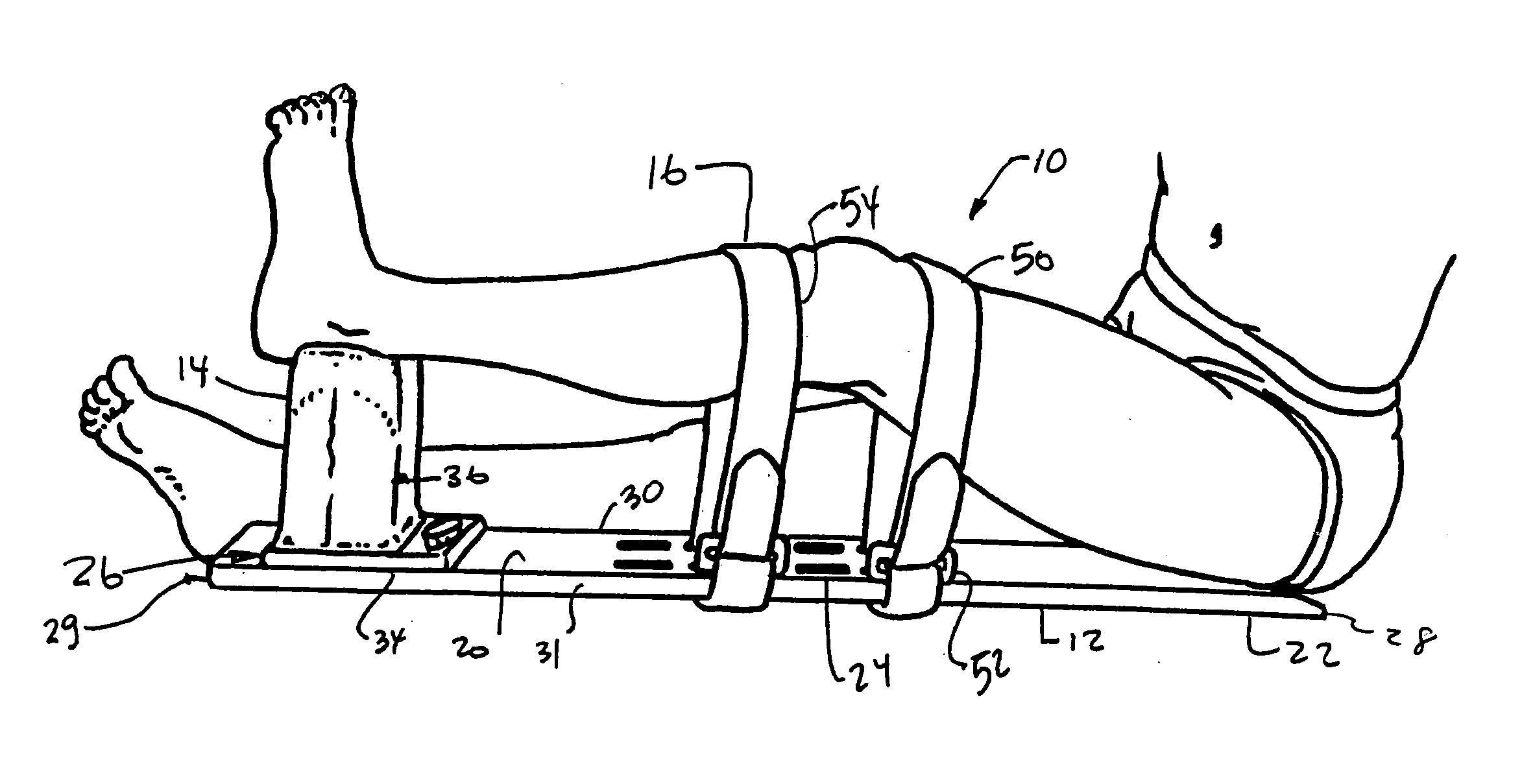
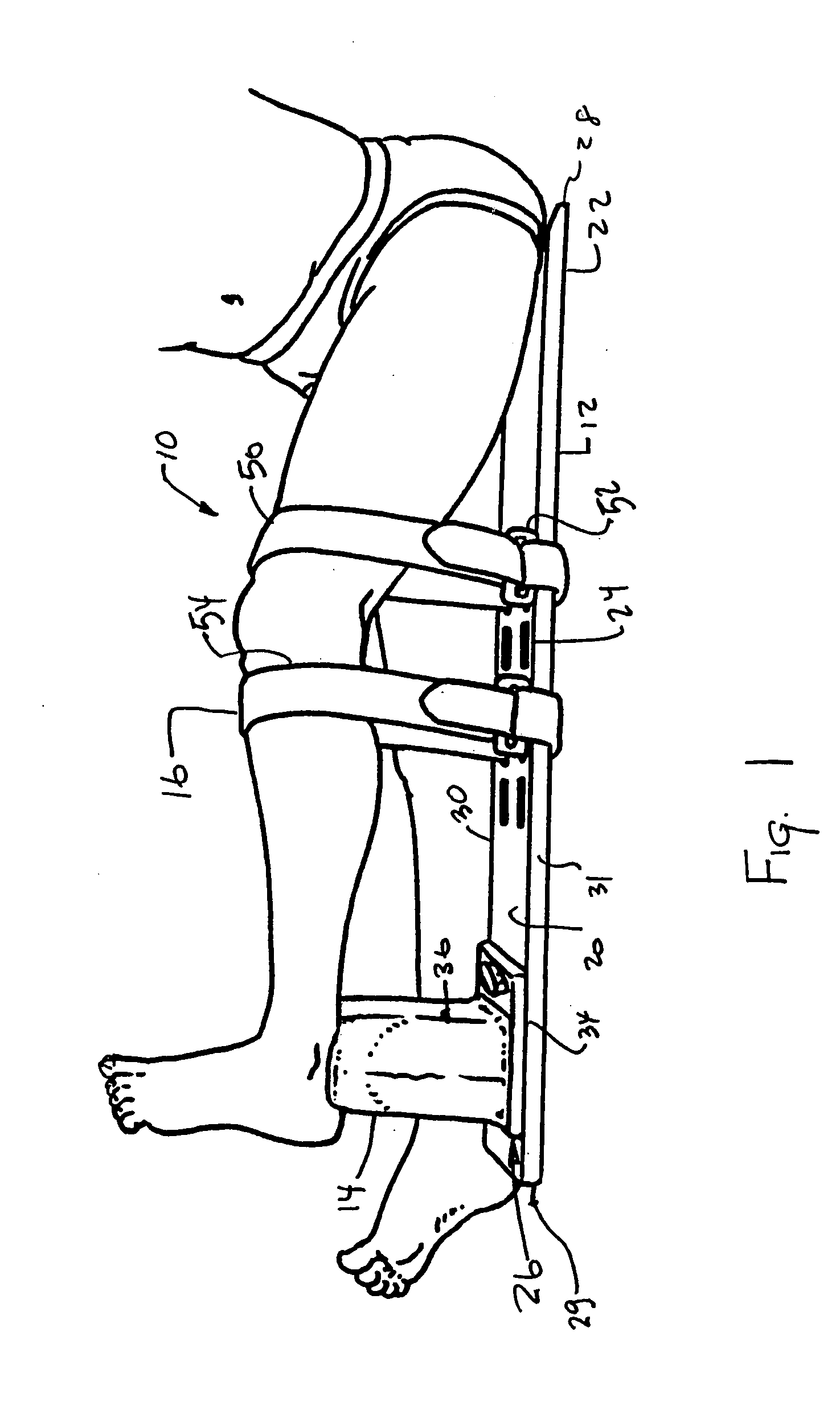
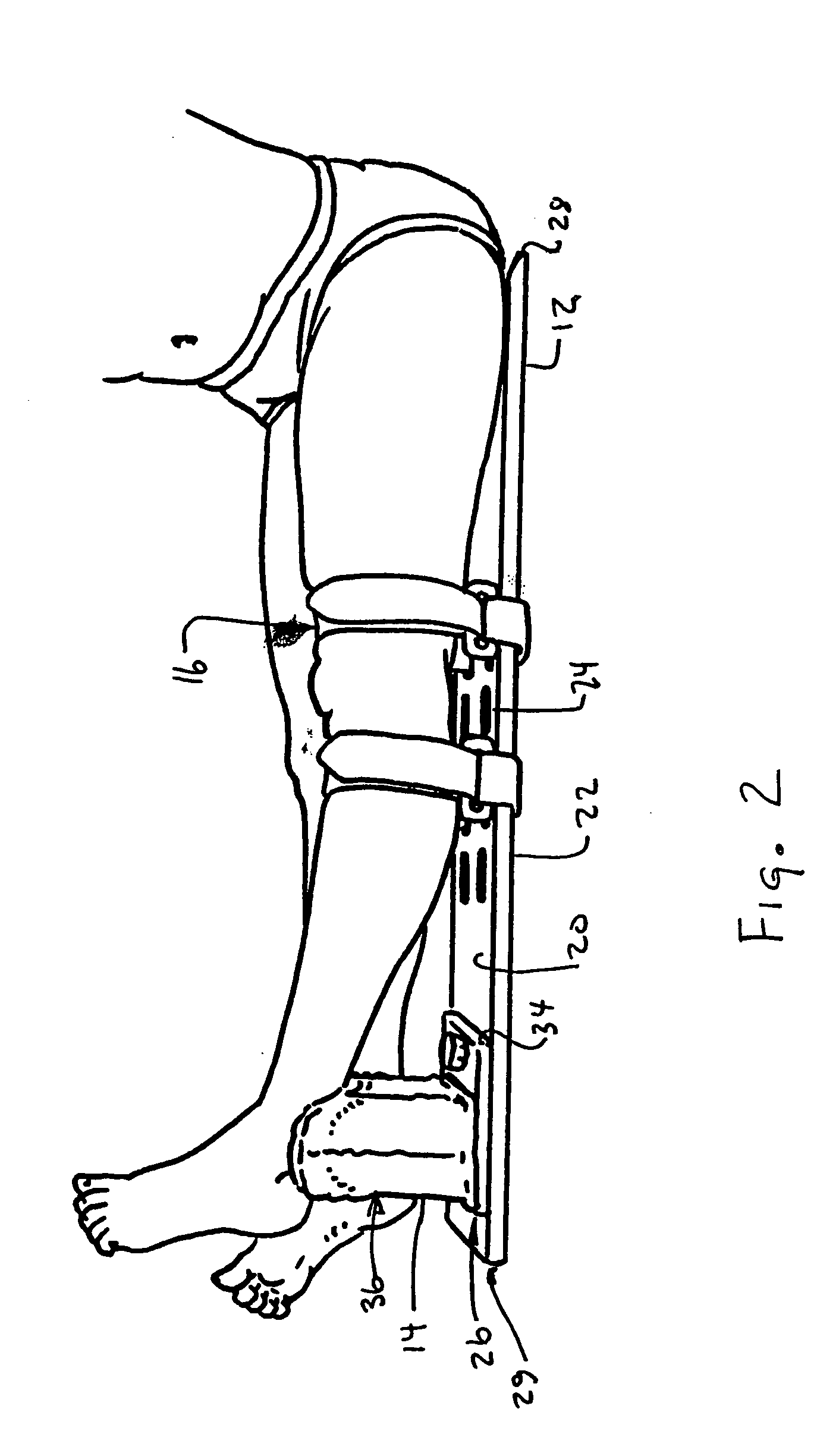
[0010] The invention comprises a knee extension apparatus for assisting a patient to extend a knee. The knee extension comprises a base, a pad assembly and at least one strap member. The base includes an upper surface, a lower surface, a first end and a second end. The pad assembly includes a pad member and a mounting assembly. The mounting assembly facilitates attachment of the pad member in at least two different locations along the upper surface of the base, proximate the second end thereof, so as to vary the distance between the first end and the pad member. The at least one strap member is associated with the base and positioned between the first end and the second end of the base member. The at least one strap member capable of retaining a leg of a patient along with the base proximate a knee portion thereof.
[0020] In a preferred embodiment, the mounting assembly facilitates attachment of the pad member to the base at a plurality of discrete locations.
[0021] In another preferred embodiment, the mounting assembly facilitates attachment of the pad member to the base at any location along a predetermined range of the base.
[0022] In another preferred embodiment, the mounting assembly facilitates slidable attachment of the pad member to the base at any location along a predetermined range of the base.

Problems solved by technology

Many injuries of the knee and lower extremities result in an inability of a patient to fully extend the knee.
Among other problems, such devices are often difficult to configure for a specific user, and, are often difficult to fit for a plurality of users.
For example, users that are not of a narrow range of height (and leg length) often experience difficulties with respect to proper usage and comfort of prior art devices.
Accordingly, treatment is generally adversely affected.
While such a material is generally acceptable for certain components, it often lacks the necessary rigidity for use in other components such as the base thereof.
As a result, treatment is again adversely affected.

Method used


Image

  • Knee extension apparatus
  • Knee extension apparatus
  • Knee extension apparatus

Examples


Embodiment Construction

[0028] While this invention is susceptible of embodiment in many different forms, there is shown in the drawings several specific embodiments with the understanding that the present disclosure is to be considered as an exemplification of the principles of the invention and is not intended to limit the invention to the embodiments illustrated.

[0029] It will be understood that like or analogous elements and / or components, referred to herein, are identified throughout the drawings by like reference characters. In addition, it will be understood that the drawings are merely representations of the present invention, and some of the components may have been distorted from actual scale for purposes of pictorial clarity.

[0030] Referring now to the Figures, and in particular to FIG. 1, knee extension apparatus 10 comprises base 12, pad assembly 14 and strap members, such as strap member 16. Base 12 comprises an elongated member having upper surface 20, lower surface 22, strap slots, such a...


PUM


Abstract

A knee extension apparatus comprising a base, a pad assembly and at least one strap member. The base includes a first end and a second end. The pad assembly includes a pad member and a mounting assembly. The mounting assembly facilitates attachment of the pad member in at least two different locations along the upper surface of the base, proximate the second end thereof, so as to vary the distance between the first end and the pad member. The at least one strap member is associated with the base and positioned between the first end and the second end of the base member. The at least one strap member is capable of encircling a leg of a patient proximate a knee portion thereof.

Description

CROSS REFERENCE TO RELATED APPLICATION [0001] This application claims the benefit of U.S. Provisional Application Ser. No. 60 / 479,553 filed Jun. 18, 2003 entitled “Knee Extension Apparatus,” the entire specification of which is incorporated by reference.BACKGROUND OF THE INVENTION [0002] 1. Field of the Invention [0003] The present invention relates in general to a physical therapy device, and more particularly, to a knee extension apparatus which facilitates and assists a patient to gradually extend the knee. [0004] 2. Background Art [0005] Many injuries of the knee and lower extremities result in an inability of a patient to fully extend the knee. As such, patients are generally required to undertake a plurality of hours of physical therapy wherein the therapist exercises and treats the knee. As a part of this therapy, the patient is often placed in a number of different devices designed to assist the patient with the extension of the knee. [0006] Among other problems, such device...

Claims


Application Information

Patent Timeline
IPC IPC(8): A61F5/00A61H1/02
CPCA61H1/0237
Inventor MARCH, PHILLIPHOP, JOHN
Owner DOCTORS ORDERS
Learn More