
Maintenance unit architecture for a scalable internet engine

a technology of internet engine and maintenance unit, applied in the field of data processing business practices, can solve the problems of hardware component failure, lack of flexibility of such systems, and the use of larger computer systems

Inactive Publication Date: 2005-04-14
RPX CORP
View PDF11 Cites 108 Cited by
  • Summary
  • Abstract
  • Description
  • Claims
  • Application Information

AI Technical Summary

Problems solved by technology

Most HSPs tend not to utilize these larger computer systems because of the expense, complexity, and lack of flexibility of such systems.
One weakness in managing server systems and the physical hardware that make up the computer systems is the possibility of hardware component failure.
In this instance, server systems are known to go into a failover mode.
The problem with these types of mirroring or shadowing arrangements is that they can be expensive and wasteful, particularly where the secondary computer system is idled in a standby mode waiting for a failure of the primary computer system.
Even with the use of such predefined computing pods, the physical preparation and installation of such pods into an administrative group can take up to a week to accomplish.
All of these solutions can work to automatically manage and balance workloads and route around hardware failures within an administrative group based on an existing hardware computing capacity; however, few solutions have been developed that allow for the automatic deployment of additional hardware resources to an administrative group.
While this solution allows the administrative group to respond appropriately during times of peak demand, the extra hardware resources allocated to meet this peak demand are underutilized at most other times. As a result, the cost of providing hosted services for the administrative group is increased due to the underutilization of hardware resources for this group.

Method used


Image

  • Maintenance unit architecture for a scalable internet engine
  • Maintenance unit architecture for a scalable internet engine
  • Maintenance unit architecture for a scalable internet engine

Examples


Embodiment Construction

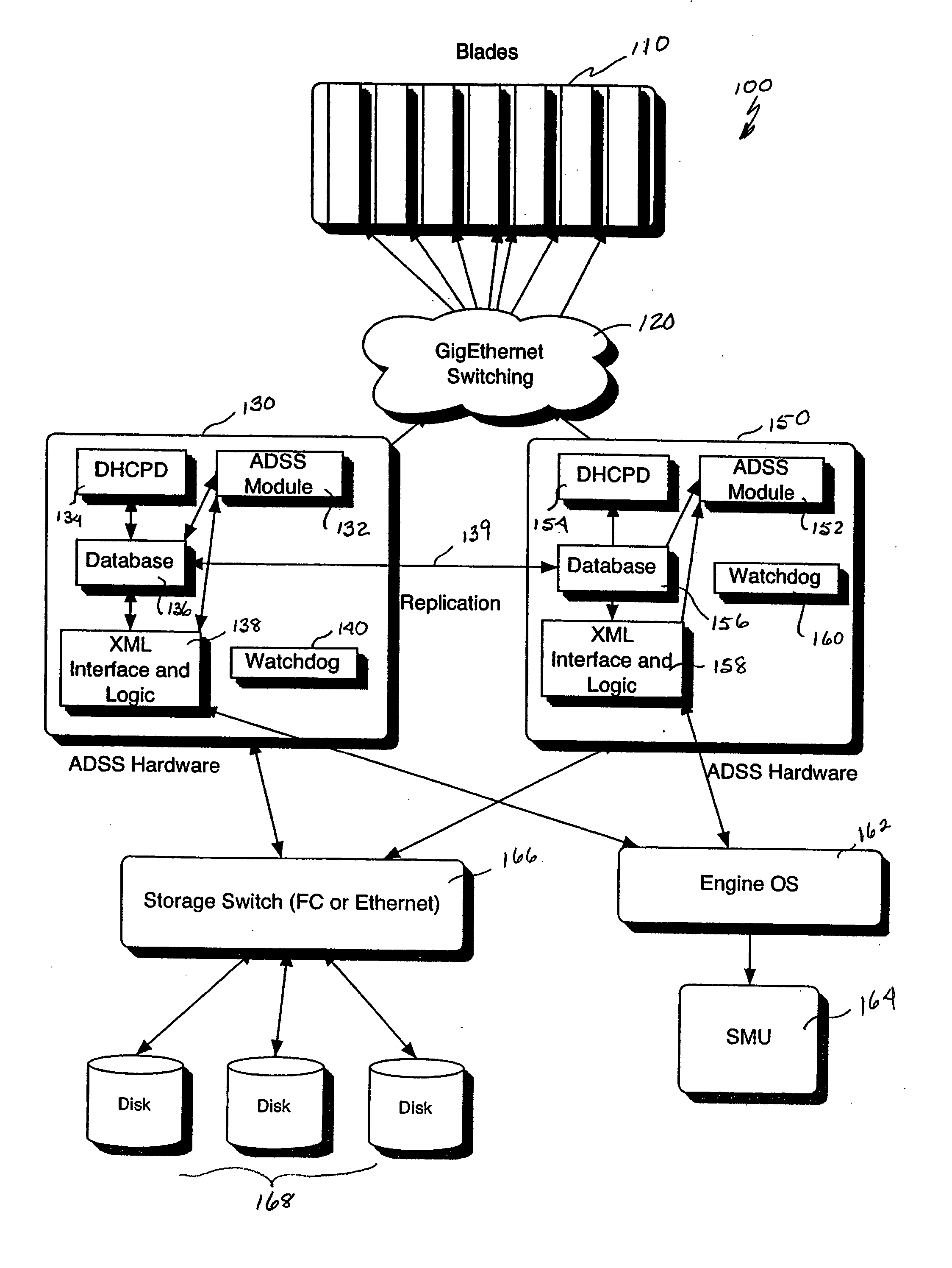
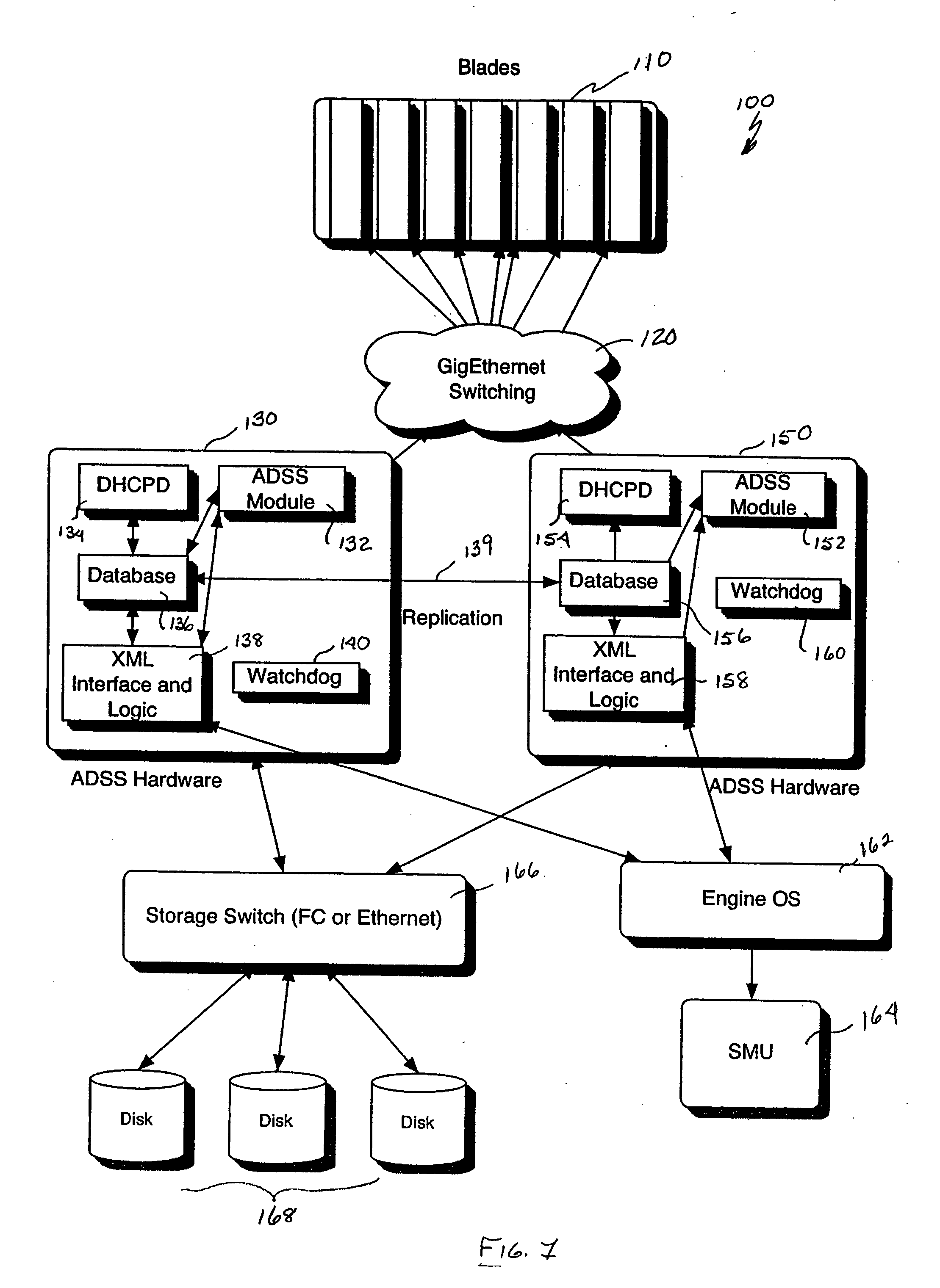
[0026] Referring to FIG. 1, an architecture 100 for a scalable Internet engine is defined by a plurality of server boards each arranged as an engine blade 110. Further details as to the physical configuration and arrangement of computer servers 110 within a scalable internet engine 100 in accordance with one embodiment of the present invention are provided in U.S. Pat. No. 6,452,809, entitled “Scalable Internet Engine,” which is hereby incorporated by reference, and the concurrently filed application entitled “iSCSI Boot Drive Method and Apparatus for a Scalable Internet Engine.” The preferred software arrangement of computer servers 110 is described in more detail in the previously referenced application entitled “Method and System for Providing Dynamic Hosted Services Management Across Disparate Accounts / Sites.”

[0027] The architecture of the present invention is further defined by two sets of hardware 130 and 150. Hardware 130 establishes the Active Data Storage System (ADSS) serv...


PUM


Abstract

A scalable Internet engine that dynamically reassigns server operations in the event of a failure of an ADSS (Adaptive Data Storage System) server. A first and a second ADSS server mirror each other and include corresponding databases with redundant data, domain host control protocol servers, XML interfaces and watchdog timers. The ADSS servers are communicatively coupled to at least one engine operating system and a storage switch; the storage switch being coupled to at least one storage element. The second ADSS server detects, via a heartbeat monitoring algorithm, the failure of the first ADSS server and automatically initiates a fail over action to switch over functions to the second ADSS server. The architecture also includes a supervisory data management arrangement that includes a plurality of reconfigurable blade servers coupled to a star configured array of data management units.

Description

PRIORITY CLAIM [0001] The present application claims priority to U.S. Provisional Application No. 60 / 498,447 entitled “MAINTENANCE UNIT ARCHITECTURE FOR A SCALABLE INTERNET ENGINE,” filed Aug. 28, 2003; U.S. Provisional Application No. 60 / 498,493 entitled “COMPUTING HOUSING FOR BLADE WITH NETWORK SWITCH,” filed Aug. 28, 2003; and U.S. Provisional Application No. 60 / 498,460 entitled, “iSCSI BOOT DRIVE SYSTEM AND METHOD FOR A SCALABLE INTERNET ENGINE,” filed Aug. 28, 2003, the disclosures of which are hereby incorporated by reference. Additionally, the present application incorporates by reference U.S. patent application Ser. No. 09 / 710,095 entitled “METHOD AND SYSTEM FOR PROVIDING DYNAMIC HOSTED SERVICE MANAGEMENT ACROSS DISPARATE ACCOUNTS / SITES,” filed Nov. 10, 2000.FIELD OF THE INVENTION [0002] The present invention relates generally to the field of data processing business practices. More specifically, the present invention relates to a method and system for dynamically and seamle...

Claims


Application Information

Patent Timeline
Patent Type & Authority Applications(United States)
IPC IPC(8): G06F15/173H04L69/40
CPCG06F11/2023H04L69/329G06F11/2033G06F11/2035G06F11/2041G06F11/2046G06F11/2097H04L61/2015H04L67/1097H04L67/1008H04L67/1029H04L67/1034H04L67/02H04L67/1002H04L69/40H04L67/1017G06F11/2028H04L61/5014H04L67/1001
Inventor CAUTHRON, DAVID M.
Owner RPX CORP
Learn More