Safety controller with safety response time monitoring

a safety controller and safety response technology, applied in the field of industrial controllers, can solve the problems of cumbersome practice of hard-wired safety systems using duplicate wiring

Active Publication Date: 2005-04-14
ROCKWELL AUTOMATION TECH
View PDF21 Cites 13 Cited by
  • Summary
  • Abstract
  • Description
  • Claims
  • Application Information

AI Technical Summary

Benefits of technology

The present invention allows for the determination of the time it takes for a signal to propagate through a network of components. By comparing this time to a threshold, the invention can enter a safety state even before the signal has fully propagated. This results in faster safety applications than would be possible based on the worst-case propagation delay of the components.

Problems solved by technology

The present invention is about improving the reliability and safety of industrial controllers used for real-time control of industrial processes. The problem that this invention addresses is the difficulty and cost of installing and maintaining hardwired safety systems due to the cumbersome and troubleshooting difficulties of such systems. The invention proposes the use of industrial controllers that can implement safety systems using a program simulating the operation of the physical components in hard-wired safety systems. However, the speed of propagation of safety signals through the components of the industrial controller must be well characterized to avoid safety processes requiring response speeds that exceed the capabilities of the controller.

Method used


Image

  • Safety controller with safety response time monitoring
  • Safety controller with safety response time monitoring
  • Safety controller with safety response time monitoring

Examples


Embodiment Construction

[0032]“High reliability” and “safety” systems are those that guard against the propagation of erroneous data or signals by detecting error or fault conditions and signaling their occurrence and / or entering into a predetermined fault state. High reliability systems may be distinguished from high availability systems which attempt to remain operating after some level of failure. The present invention may be useful in both systems, however, and therefore, as used herein, high reliability and safety should not be considered to exclude high availability systems that provide safety operation.

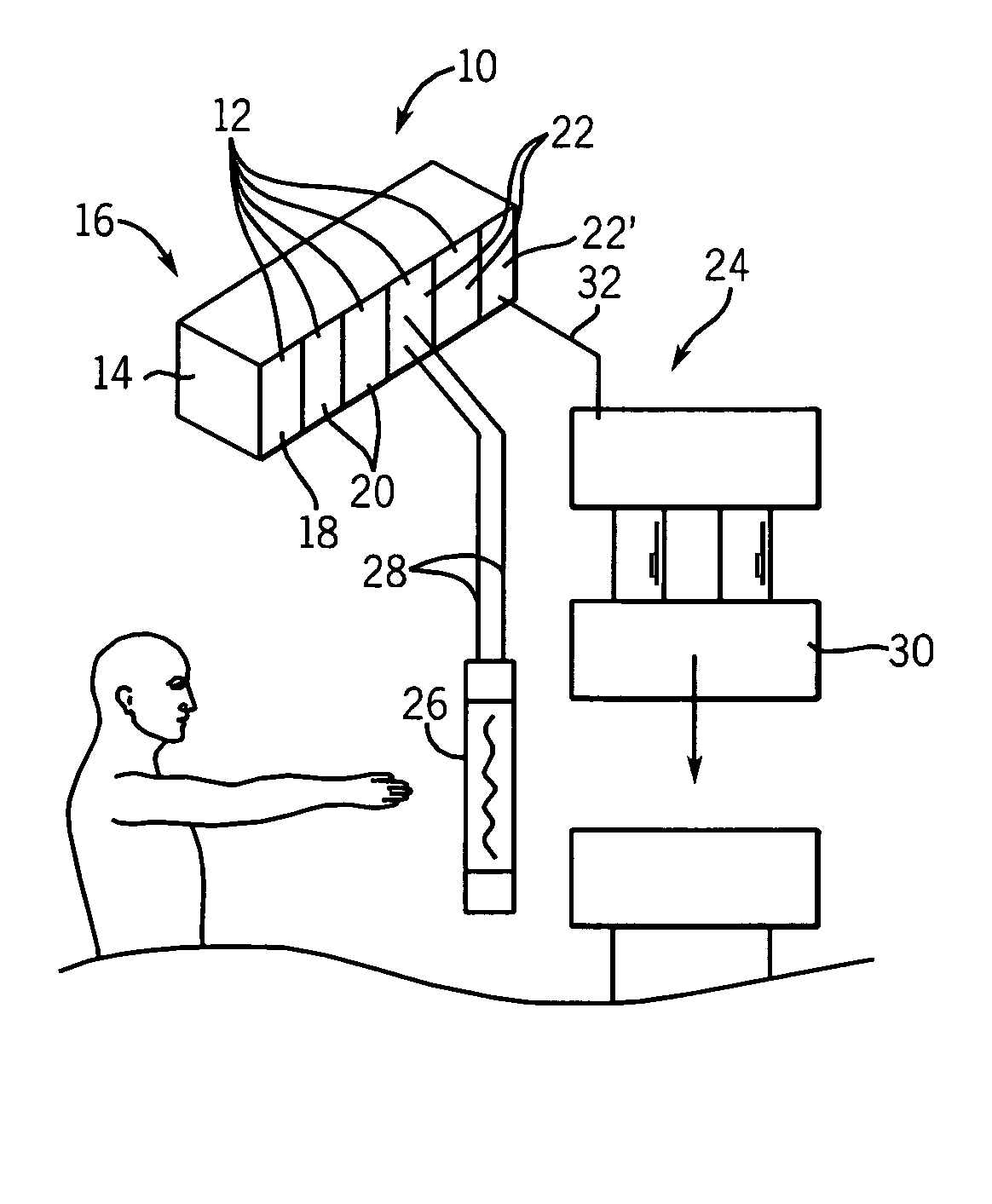
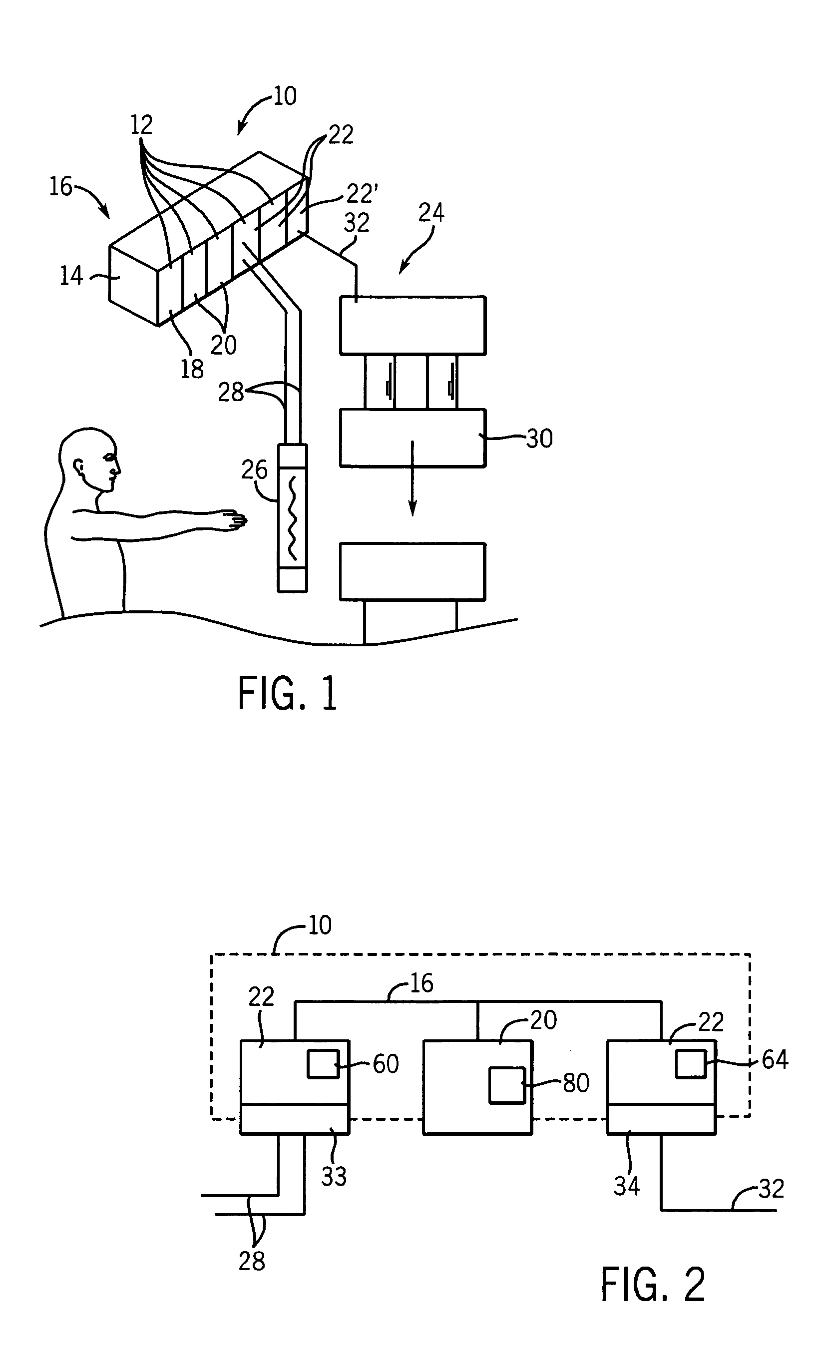
[0033] Referring now to FIG. 1, a safety controller 10 may include generally a plurality of modules 12 held in a rack 14 for intercommunication along a backplane 16, the backplane 16 providing an electrical channel of communication between the modules 12. Alternatively, the backplane may be any generalized serial communication network.

[0034] The modules 12 may include a power supply module 18 provid...


PUM

PropertyMeasurementUnit
Timeaaaaaaaaaa
Safety-related propertiesaaaaaaaaaa

Abstract

A safety controller having a total worst case propagation delay, exceeding the required propagation delay required by a safety process, may be used to control the safety process by monitoring actual delays in signal processing in the safety controller and moving to a safety state if a signal delay exceeds an amount less than the total worst case propagation delay.

Description


Claims


Application Information

Patent Timeline
Owner ROCKWELL AUTOMATION TECH
Why Eureka
Try Eureka