Masonry wall tension device and method for installing same

a technology of tension device and masonry wall, which is applied in the direction of walls, building components, structural elements, etc., can solve the problems of not strengthening adjacent units, masonry walls tend to vibrate back and forth, and the method of strengthening masonry walls suffers from various problems

Inactive Publication Date: 2005-04-21
CRUMLEY HARVEL K
View PDF14 Cites 25 Cited by
  • Summary
  • Abstract
  • Description
  • Claims
  • Application Information

AI Technical Summary

Problems solved by technology

However, this method for strengthening masonry walls suffers from various problems.
As a result, the masonry wall tends to vibrate back and forth during strong seismic movements or strong winds.
Additionally, filling the cells or voids of the masonry units, strengthens the masonry units around these c

Method used


Image

  • Masonry wall tension device and method for installing same
  • Masonry wall tension device and method for installing same
  • Masonry wall tension device and method for installing same

Examples


Embodiment Construction

[0029] The present invention may be best understood by reference to the attached drawings wherein FIG. 1 shows the usage of the invention, and the remaining FIGS. Illustrate various embodiments of the tension device.

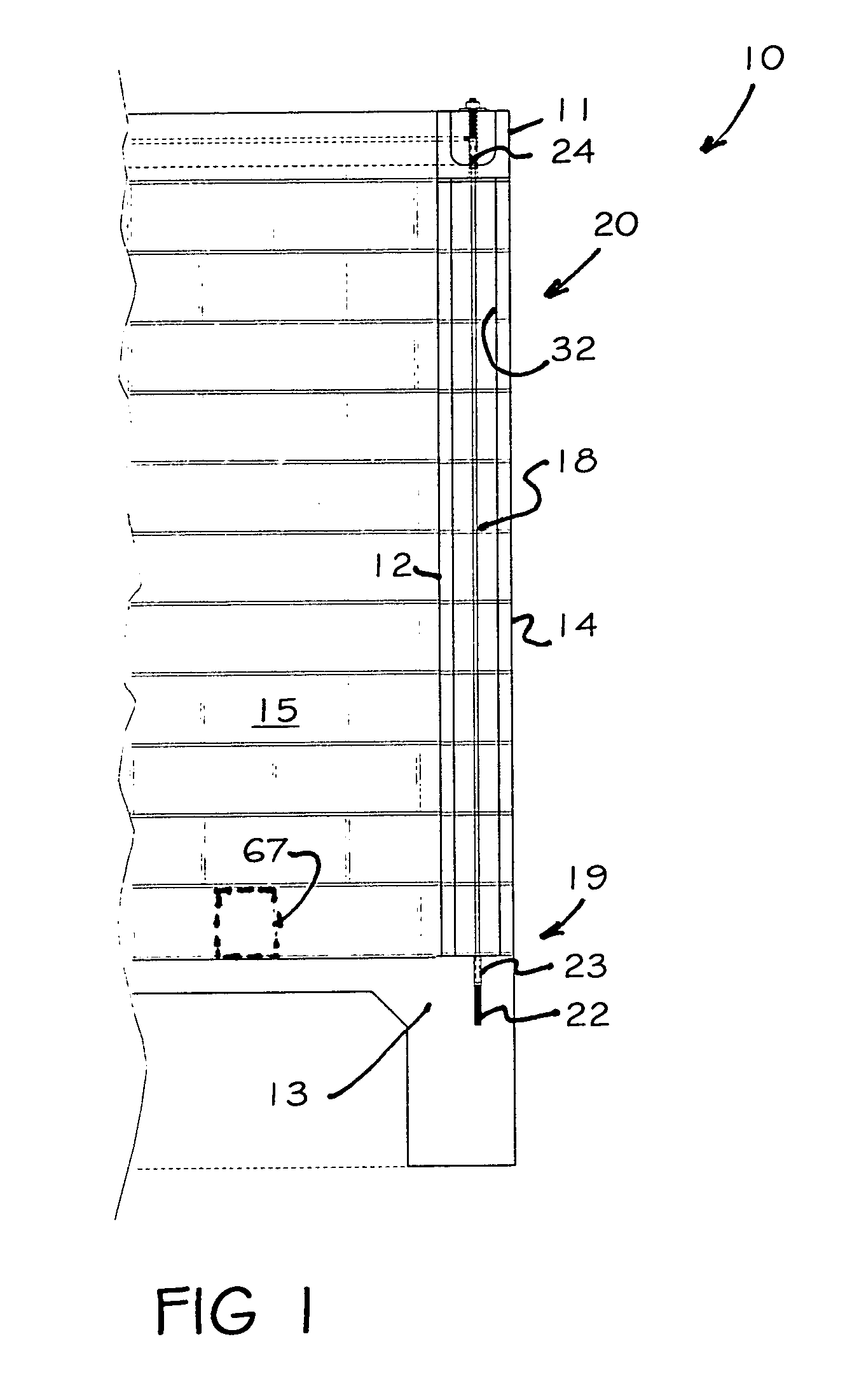
[0030] In FIG. 1 a partial section of a masonry building is shown at numeral 10. The building includes at least two masonry walls 12 supported on a concrete foundation 13. A continuous bond beam 11 is laid on top of the masonry walls 12 to strengthen the walls. Each of the masonry walls 12 includes a plurality of vertical hollow wall sections 14 having a number of hollow masonry units 15, laid over each other.

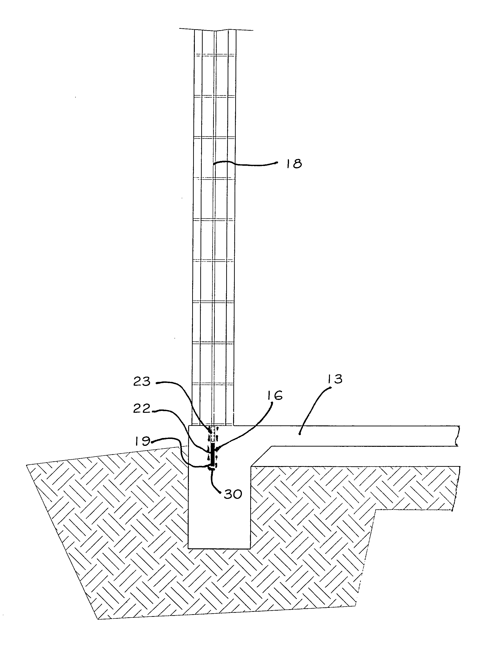
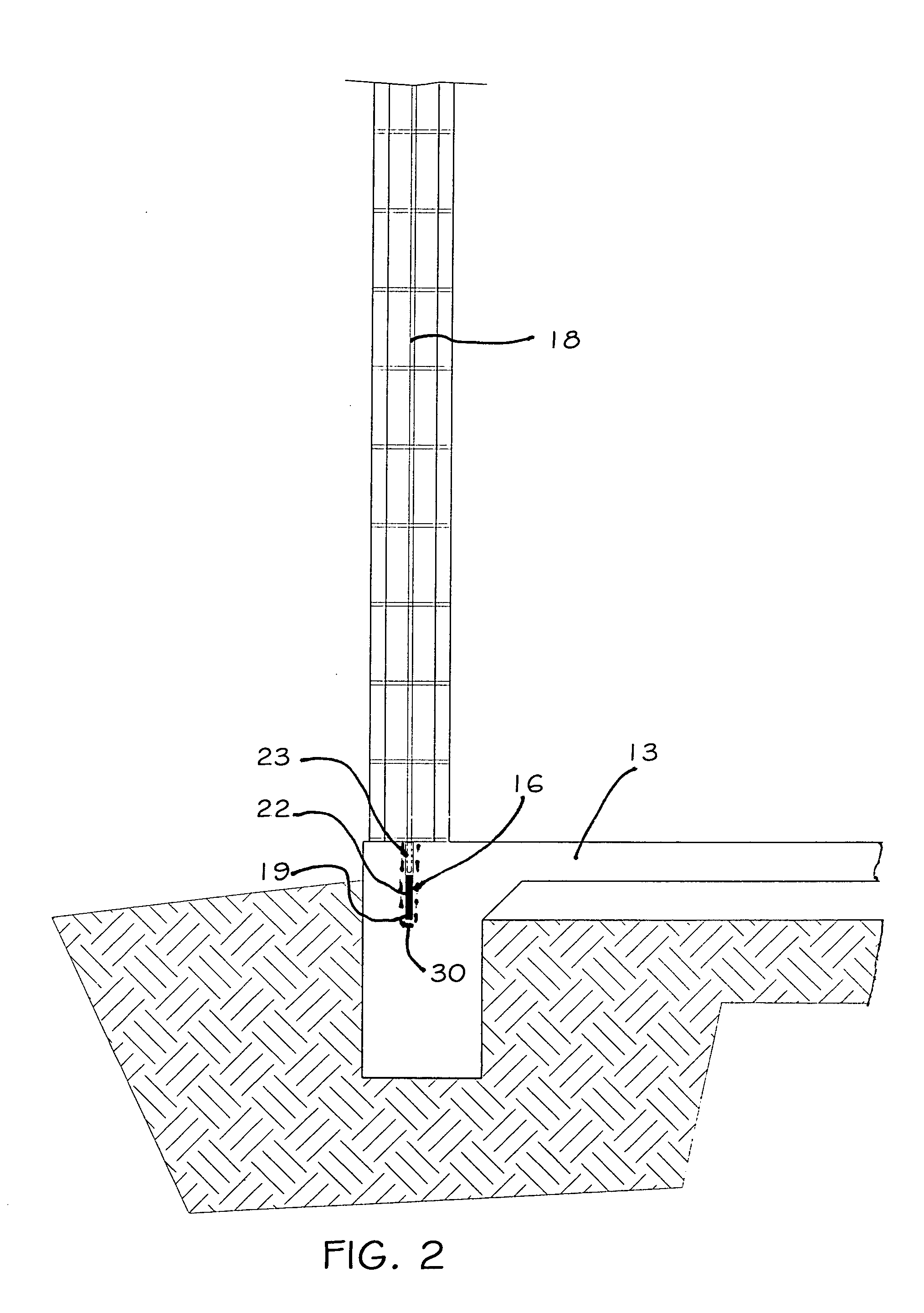
[0031]FIG. 1 shows a tensioning device, an elongated member 18, installed in a hollow masonry wall 12. The member 18 extends through and above the bond beam 11 located at the top of the masonry wall 12 and is secured to a foundation 13, by securing means such as epoxy resin adhesive. The member 18 ties the masonry wall 12 with the bond beam 11 and the concrete fou...


PUM


Abstract

Masonry walls of buildings supported on concrete foundations are strengthened against destructive wind and seismic forces by spaced elongated members inserted inside the hollow masonry walls. The spaced elongated members are secured to the continuous masonry bond beam and the foundation. Tension means at the top of the masonry wall make the elongated members taut creating a continuous tension load path from bond beam to the foundation.

Description

CROSS-REFERENCE TO RELATED APPLICATION [0001] Not Applicable STATEMENT REGARDING FEDERALLY SPONSORED RESEARCH OR DEVELOPMENT [0002] Not Applicable REFERENCE TO A MICROFICHE APPENDIX [0003] Not Applicable BACKGROUND OF THE INVENTION [0004] Masonry structures predominate in residential and light commercial construction. In order to provide protection from strong winds, tornadoes, hurricanes, and seismic activity, builders reinforce installed masonry walls by filling cells of the masonry wall with concrete and steel bars at selected locations. The number of the reinforced cells, the quantity of concrete and the number of bars used vary depending on the severity of the wind and the geometry of the structure. [0005] Masonry structures can also be strengthened during installation. Masonry units are laid over the reinforcing bars so that the bars are in the center of the cell within the masonry unit. Builders install additional reinforcing bars inside the voids and pour concrete around the...

Claims


Application Information

Patent Timeline
IPC IPC(8): E04B1/35E04B2/02E04H9/14
CPCE04B2001/3583E04H9/14E04B2002/0254
Inventor CRUMLEY, HARVEL K.
Owner CRUMLEY HARVEL K
Why Eureka
Try Eureka