
Force element for vehicle impact crash simulator

a technology of force element and crash simulator, which is applied in the direction of vehicle testing, structural/machine measurement, instruments, etc., can solve the problems of negative acceleration, increase in velocity and positive acceleration of sled, and difficulty in properly simulation, so as to achieve more efficient and effective testing

Inactive Publication Date: 2005-04-21
MTS SYSTEMS CORPORATION
View PDF24 Cites 50 Cited by
  • Summary
  • Abstract
  • Description
  • Claims
  • Application Information

AI Technical Summary

Benefits of technology

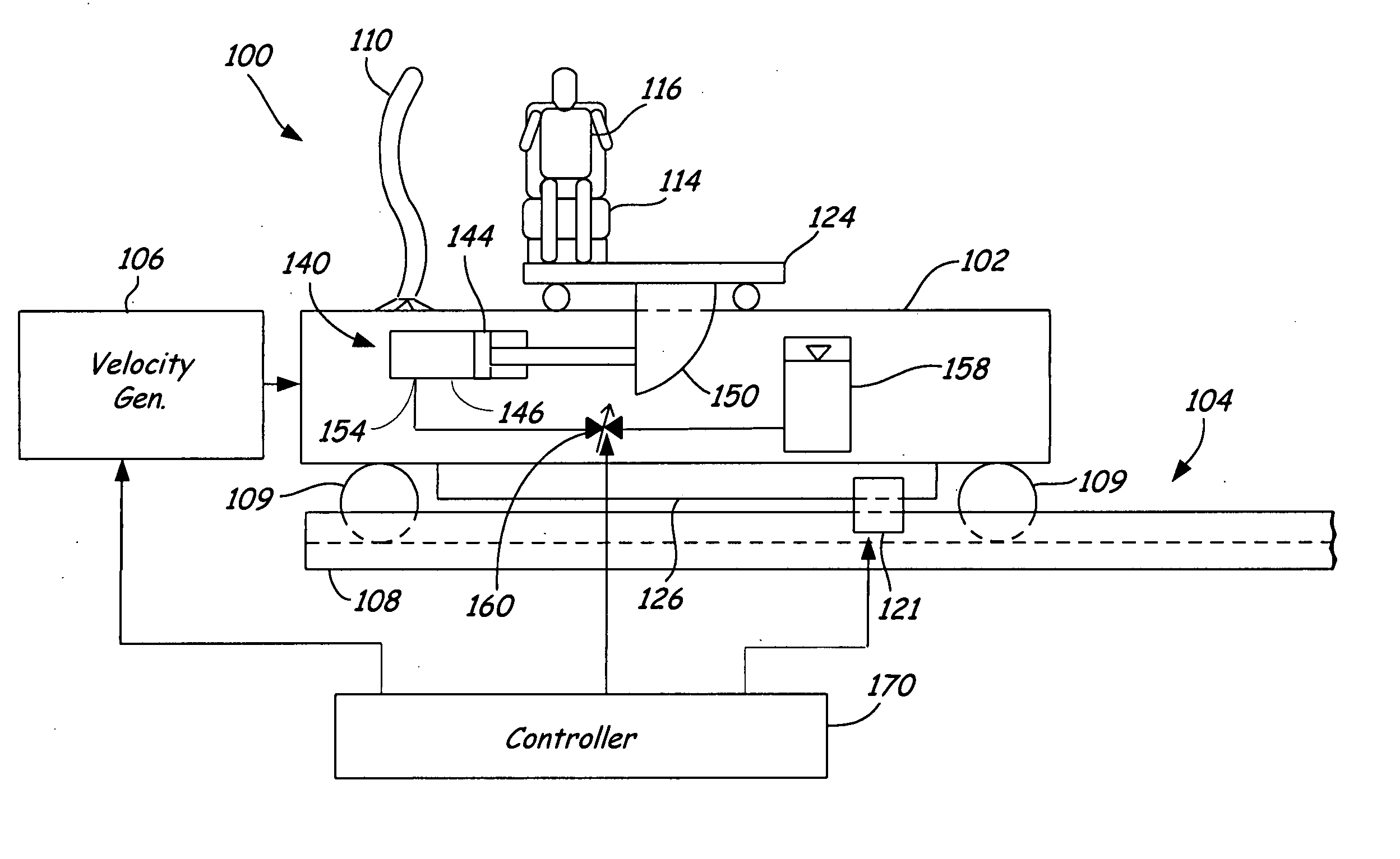
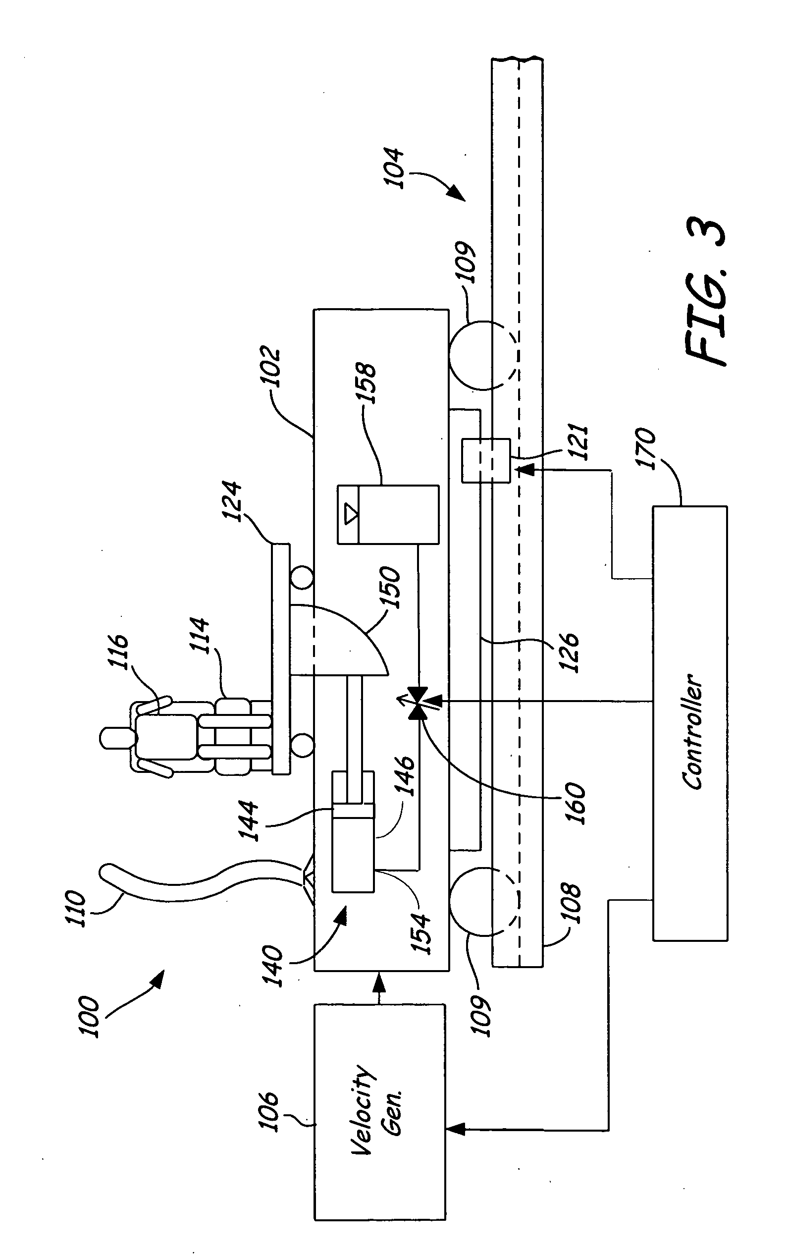
[0009] Embodiments of a crash simulator sled assembly are disclosed. The crash simulator sled assembly can include a sled, an element movable relative to the sled, and a force element such as a damper assembly or actuator assembly coupled to the element. A second sled can also be connected to the element. The damper assembly can control relative movement of the element relative to the sled, while the actuator can develop force to replace force attributable to mass. This provides advantages for more efficient and effective test crash simulation and research.

Problems solved by technology

In particular, the velocity generator causes an increase in velocity and positive acceleration of the sled, while a braking device slows the sled down and thereby induces a negative acceleration.
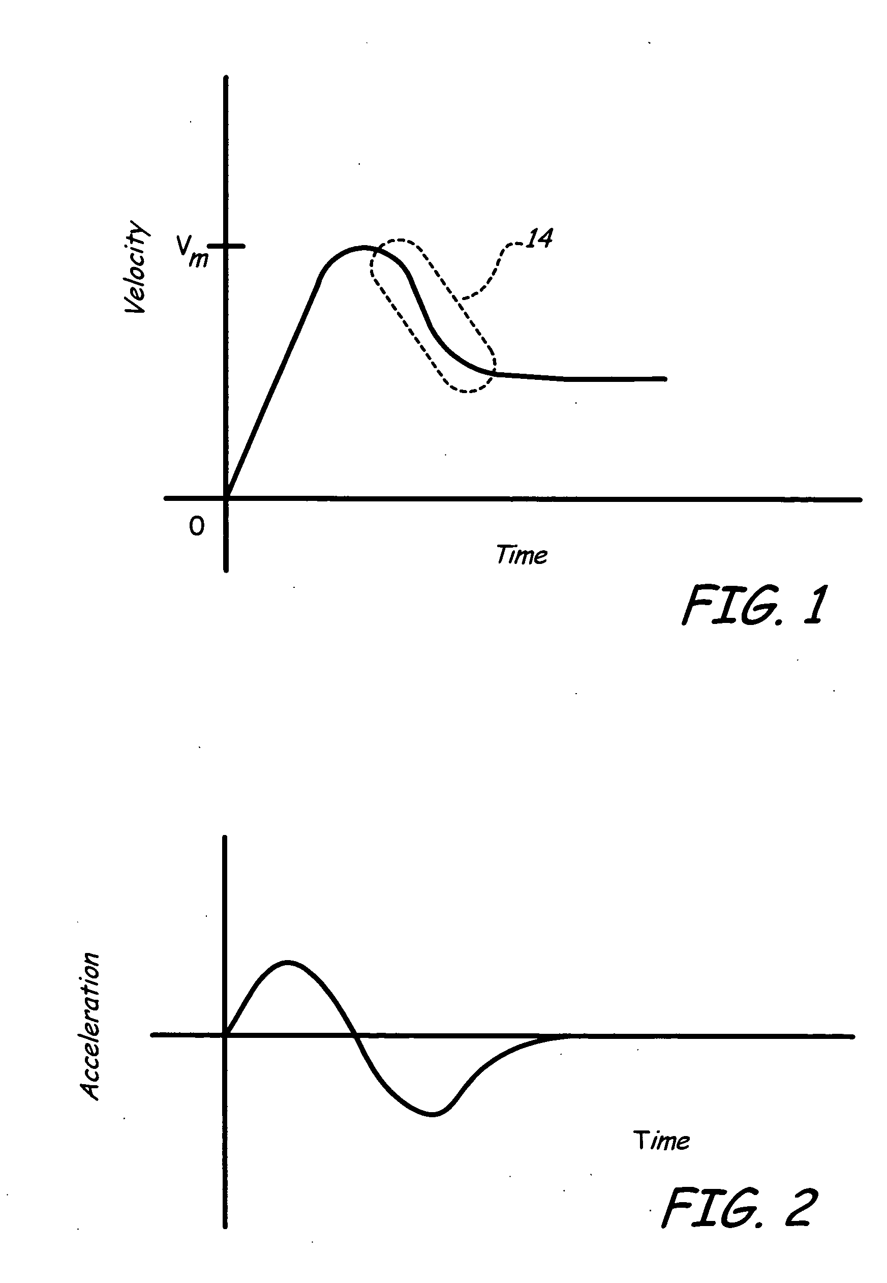
Nevertheless, due to the relative velocity of the door and the test dummy / seat it is difficult to properly simulate region 14 (FIG. 1) using current test apparatuses and methods.

Method used


Image

  • Force element for vehicle impact crash simulator
  • Force element for vehicle impact crash simulator
  • Force element for vehicle impact crash simulator

Examples


second embodiment

[0028] In the embodiment of FIG. 3, generally, the door is pre-deformed and fixed to the sled 102. Thus, this embodiment does not deform the door in real-time. FIG. 4 is the present invention where deformation of the door occurs in real-time. In an embodiment of FIG. 4, sled 102 includes a crushable element 200 such as a honeycomb structure that simulates crushing of the front portion of the bullet car. The crushable element 200 is mounted to a support 202 of the sled 102. In this embodiment, the door 110 is mounted to the platform 124 along with the seat 114. A structural element 203 can couple the door 110 and the seat 114 together, in one embodiment. Structural element 203 may be an actual portion or segment of the vehicle's structure between door 110 and seat 114, or a crushable element that simulates this portion of the vehicle, in various embodiments. However, in a further embodiment, a damper assembly as illustrated in FIG. 3, can be used between the vehicle seat 114 and the ...

third embodiment

[0032]FIG. 5 is the present invention, where deformation of the door occurs in real-time, similarly to the embodiment of FIG. 4. In an embodiment of FIG. 5, many components are similar in structure and function to the embodiment of FIG. 4 as described above. These include crushable element 200, support 202, door 110, platform 124, seat 114, tracks 108, velocity generator 106, controller 170, braking device 121, and test dummy 116.

[0033] In this embodiment, sleds 502 and 522 are coupled to tracks 108. Platform 124 is securely coupled to sled 522, and is operably coupled to sled 502 with a damper assembly 524 similar to the type described above with respect to FIG. 3. In this embodiment, damper assembly 524 is provided wherein a plunger 526 is coupled to the platform 124 via gusset 540, while a cylinder 528 is fixed to the first sled 502. A valve mechanism 560 controls fluid flow from the cylinder 528 to a reservoir 530. As appreciated by those skilled in the art, the location of cyli...


PUM


Abstract

Embodiments of a crash simulator sled assembly are disclosed. The crash simulator sled assembly can include a sled, an element movable relative to the sled, and a force element, such as a damper assembly or actuator assembly, coupled to the element. A second sled can also be connected to the element. The damper assembly can control relative movement of the element relative to the sled, while the actuator can develop force to replace force attributable to mass. This provides advantages for more efficient and effective test crash simulation and research.

Description

CROSS REFERENCE TO RELATED APPLICATION [0001] The present application is based on and claims the benefit of U.S. provisional patent application Ser. No. 60 / 489,422, filed Jul. 23, 2003, the content of which is hereby incorporated by reference in its entirety.BACKGROUND OF THE INVENTION [0002] The present invention relates generally to vehicle crash simulators. [0003] A vehicle crash simulator simulates dynamics of a crash to evaluate vehicle occupant safety and conditions during a crash event. A crash simulator uses data from an actual test crash or computer simulation to physically simulate movement of a vehicle during a crash for evaluation. During a simulated crash, velocity is imparted by a velocity generator to a base sled carrying a specimen to simulate vehicle acceleration. Sensors and instruments on stationary mounts or on board the simulation apparatus or specimen collect test data for evaluation. [0004] During a side impact crash, a “bullet car”, i.e. a moving car, strikes...

Claims


Application Information

Patent Timeline
IPC IPC(8): G01M7/08G01M17/00G01M17/007
CPCG01M17/0078
Inventor SAARI, BYRON J.ALBRIGHT, F. JOSEPHLEUER, ROSS H.
Owner MTS SYSTEMS CORPORATION
Learn More