Handle vibration dampening

Inactive Publication Date: 2005-04-21
PINGEL KENNETH A +1
View PDF9 Cites 12 Cited by
  • Summary
  • Abstract
  • Description
  • Claims
  • Application Information

AI Technical Summary

Benefits of technology

[0006] It is a further object of the present invention to provide an improved manner of reducing the vibration in a handlebar to reduce rider fatigue.
[0007] It is yet another object of the present invention

Problems solved by technology

Vibration in motorcycle handlebars, for example, can lead to fatigue for th

Method used


Image

  • Handle vibration dampening
  • Handle vibration dampening

Examples


Example

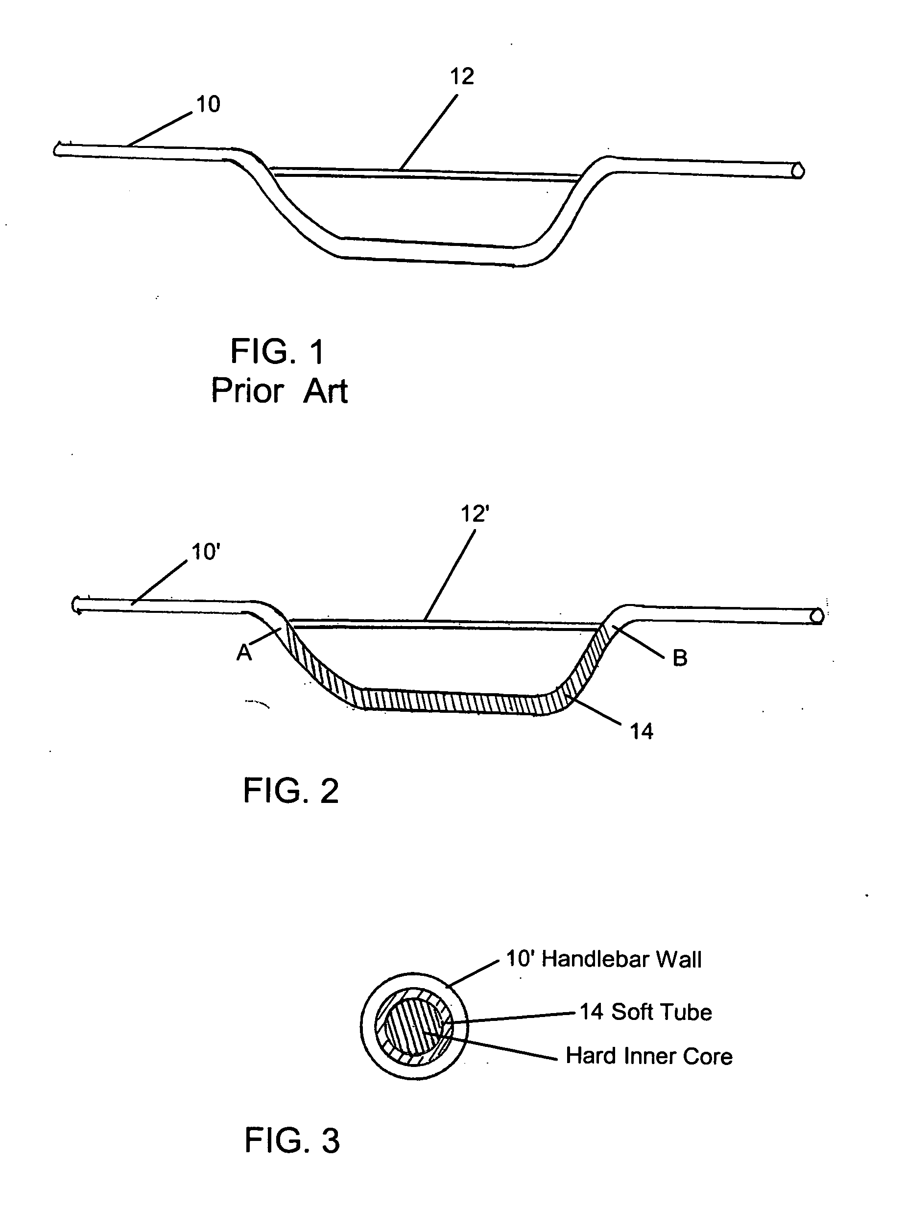
[0013] The system according to a preferred embodiment of the present invention comprises providing an insert which is placed inside the hollow tube of the handle or handlebar. The insert is typically tubular, and comprises a softer outer layer and a harder inner core. It is believed that the differences in hardness of the layers going from the handlebar wall, the outer layer and the inner layer results in a dampening effect.

[0014] Referring to FIG. 2, the invention involves inserting a soft tube 14 into the handlebar 10′, desirably to span between the points A and B of the handlebar at least, or more. Then, a harder inner core is provided to the inserted tube, suitably by injecting polyurethane into the hollow core of the inserted tube. The polyurethane then hardens after a curing period, and the result is a substantial dampening effect. The injecting can be accomplished by use of a syringe, for example. Accordingly, the invention can be provided as a kit for after market installat...


PUM


Abstract

Vibration dampening in a handle is accomplished by employing a relatively soft tube which is inserted into the interior hollow of the handle. A harder interior is provided to the tube and the interaction therebetween results in vibration dampening.

Description

BACKGROUND OF THE INVENTION [0001] This invention relates to handle vibration dampening for handlebars or the like. [0002] Vibration in motorcycle handlebars, for example, can lead to fatigue for the rider after a long time riding, and over time, can result in nerve damage. [0003] A typical handlebar is shown in FIG. 1, where the handlebar 10 is a hollow tubular member formed to a certain shape. A typical prior art type dampening bar12 is added to attempt to control some of the vibration. SUMMARY OF THE INVENTION [0004] In accordance with the invention, an insert is provided which is placed inside the hollow tube of the handle. The insert is typically tubular, and comprises a softer outer layer and a harder inner core. [0005] Accordingly, it is an object of the present invention to provide an improved handlebar vibration dampening method and apparatus [0006] It is a further object of the present invention to provide an improved manner of reducing the vibration in a handlebar to redu...

Claims


Application Information

Patent Timeline
IPC IPC(8): B62K21/14
CPCY10T74/2078B62K21/14
Inventor PINGEL, KENNETH A.MISHO, DONALD F.
Owner PINGEL KENNETH A
Why Eureka
Try Eureka