Tilt base for a router tool
Inactive Publication Date: 2005-04-21
WIELECHOWSKI ROBERT E
17 Cites 22 Cited by
AI-Extracted Technical Summary
Problems solved by technology
However, such a relatively simple tool has its limitations.
Perhaps the most obvious of these limitations is the fact that the rotational axis of the cutting bit is fixed concentrically relative to the housing and its base.
However, there are only a relatively few handheld routers which provide any means of holding the cutting axis of the tool at some predetermined angle other than normal to the plane of the base and the surface of the workpiece upon which the base is placed.
The result is a relatively inexpensive tool and attachment which provide versatility only matched by considerably more costly and more cumbersome tools.
However, the lateral offset of the router mandrel and its cutting bit from the pivot axis results in the cutting bit being raised above the plane of the work when other than normal to the work plane.
It is also noted that while Turnbull provides an adjustable lower position stop for the angular movement of his router, he does not provide any means of locking the angle of the router relative to the base.
The Turnbull router assembly does not appear to be designed for to cutting a workpiece at other than 90° to the surface of the workpiece, and the tool does not readily provide for such use.
However, Gachet et al. do not provide any means of adjusting the angle of the router itself, or of its rotary shaft and cutting bit relativ...
Benefits of technology
[0022] The router base essentially comprises a sleeve for removably and adjustably securing a router therein. Rather than having a relatively wide cutting bit end skirt completely encircling the cutting bit of the router installed therein, the present router base has two relatively wide, opposed tilt clearance areas formed in the lower portion or skirt thereof. The clearance areas are separated by opposed pivot lugs or ears which depend from the base, and which attach to corresponding lugs or ears extending upwardly from a base attachment ring. The ring is in turn secured to a base plate, which is placed upon the workpiece during operation of the router to position the router and its cutting bit as desired. Th...
Abstract
The tilt base for a handheld router tool allows a router secured therein to be tilted equally in opposite directions from a position in which the rotational axis is normal to the underlying base plate and workpiece. The tilt base includes two opposed tilt clearance areas formed in the lower skirt portion thereof, with two depending opposed pivot attachment lugs or ears separating the two tilt clearance areas. A base plate includes a pair of opposed upstanding pivot attachment fittings, to which the pivot attachment lugs of the router base attach. The base plate may be formed of opaque, translucent, or transparent material, and includes an elongate slot for cutting bit clearance when the router is tilted. The operator of the tool may quickly and easily adjust the tilt angle of the router and its base to provide angled or beveled cuts in a workpiece as desired.
Application Domain
Wood feeding arangementsFeeding devices +3
Technology Topic
Rotational axisBackplane +2
Image
Examples
- Experimental program(1)
Example
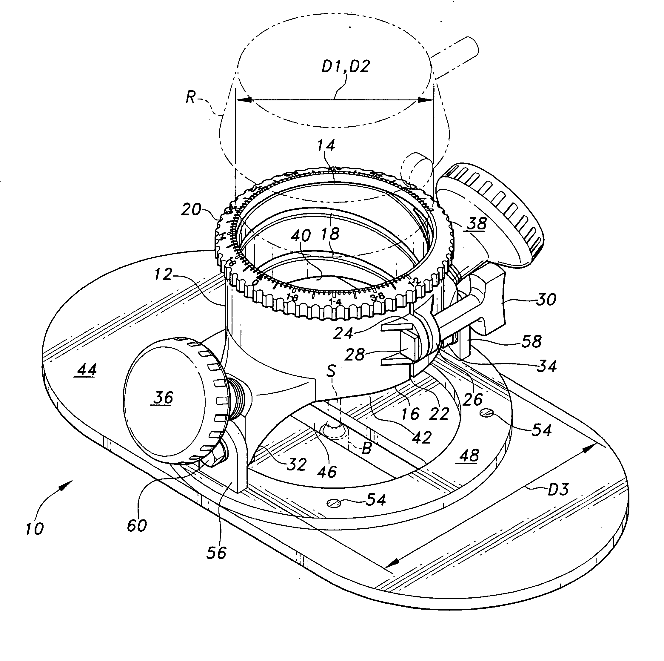
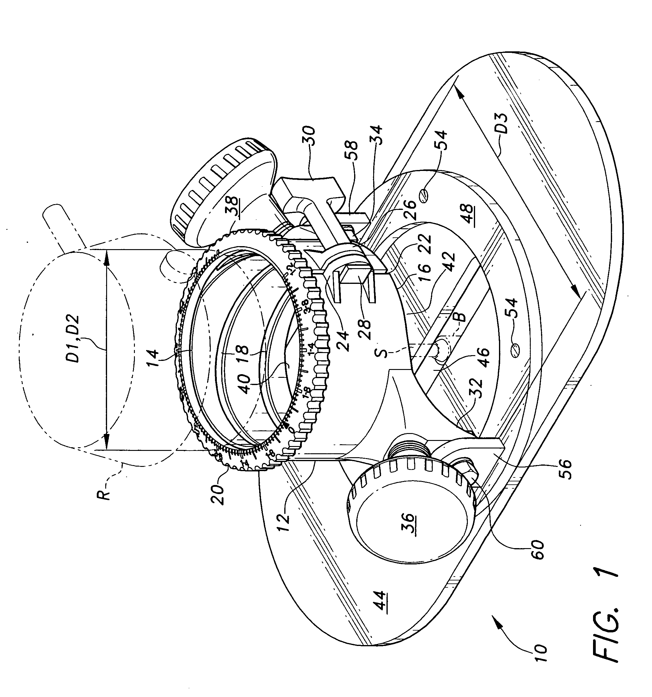
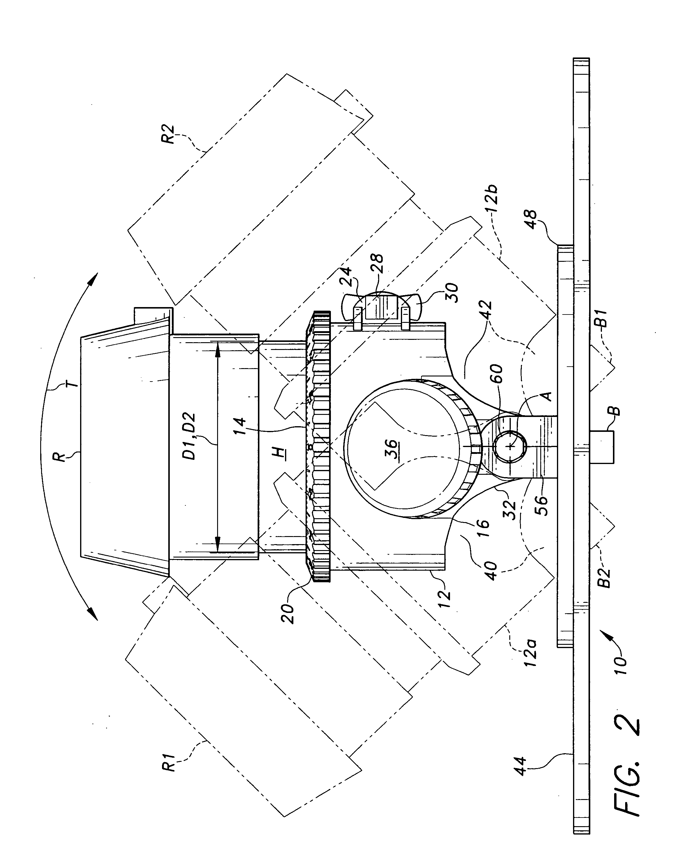
[0027] The present invention comprises a tilt base for a handheld router tool, enabling the base and the router secured therein to be tilted along a plane which passes through the centerline of the assembly and its output shaft. The term “handheld router tool” as used in the present disclosure, is not intended to indicate that the router itself is held by its outer case or housing when being used, but rather that the router is used with a freely manipulable, handheld base, as opposed to routers which are essentially permanently attached beneath a router table or the like with the cutting bit extending upwardly through an opening in the table. The tilt base of the present invention enables the operator of the device to adjust the angle of the router base relative to the underlying base plate to which it is pivotally attached, thereby allowing the operator to manipulate the router to cut or form beveled edges and other cuts where the cut face is not square with the base of the router and the surface of the workpiece.
[0028]FIG. 1 of the drawings provides a perspective view of the present tilt base assembly 10. The assembly 10 includes a router base 12, in which a handheld router tool R (shown in broken lines in FIG. 1) is removably installed. The base 12 is generally in the form of a cylindrical sleeve and is substantially symmetrical about its central axis, which is concentric with the centerline of the router R, its output shaft S, and interchangeable cutting bit B. The only asymmetric feature of the base 12 is the clamping mechanism (discussed further below) for removably securing the outer housing H (shown in FIG. 2) of the router R within the closely fitting base sleeve 12.
[0029] The router base 12 has a router installation end 14 and an opposite base plate attachment end 16, with the router output shaft S or mandrel extending from the base plate attachment end 16 of the router base 12. The internal diameter D1 of the router base sleeve 12 is substantially the same as, or only very slightly larger than, the diameter D2 of the router R, in order to provide a good fit between the two when the router R is installed within the base 12. The router R is installed in the base 12 through the installation end 14, with router height adjustment being accomplished by means of a pin (not shown) which extends radially to engage the helical slot 18 formed within the router base sleeve 12. Rotating the router R within the housing sleeve 12 results in the router R rising or descending relative to the housing 12 as the pin extending from the router R rides along the helical ramp of the slot 18, much like the advance or retreat of a threaded screw. A router height index ring 20 may be provided about the router installation end 14 of the housing 12, if so desired. Other means of adjusting the cutting height of the router R relative to the housing 12 may be provided as desired, e.g. direct axial movement or adjustment of the router R, a rack and pinion gear adjustment, etc.
[0030] The router R is locked in place within the base 12 by means of a clamp assembly disposed to one side of the base 12. A slot 22 extends from the router installation end 14 to the opposite base plate attachment end 16 of the router base 12. A clamp bolt lug or ear, respectively 24 and 26, extends outwardly from the base 12 adjacent corresponding sides of the slot 22. A clamp bolt 28 passes through the two lugs 24 and 26, with a winged fastener 30 or other suitable device engaging the threaded end of the bolt 28. The router R is inserted in the router base sleeve 12 and adjusted to the desired cutting height for the router bit B, and the winged fastener 30 is tightened to clamp the base sleeve 12 tightly about the router R to prevent movement of the router R relative to the base 12.
[0031] First and second pivot lugs, respectively 32 and 34, depend from the base plate attachment end 16 of the router base 12, with the two pivot lugs 32 and 34 being disposed laterally opposite one another. The two pivot lugs 32 and 34 depend below the outwardly extending portions of the base 12 which have the two opposed handles 36 and 38 attached thereto and extending therefrom. The handles 36 and 38 may be spaced from the pivot lugs for greater hand clearance for the user by means of one or more washers or a section of pipe or sleeve, as shown in FIG. 3. The outward offset of the two pivot lugs 32 and 34 results in a distance D3-therebetween which is substantially greater than the internal diameter D1 of the router base sleeve 12. This provides much greater clearance for viewing the routing process during the routing operation, and for accessing the cutting bit attachment collet when changing cutting bits.
[0032] The conventional router base includes a relatively wide flange or skirt which completely surrounds the output shaft and cutting bit end of the device. While such a surrounding flange or skirt provides the required stability for a router installed within the base, it prevents the base and router installed therein from being tilted; the output shaft and its attached cutting bit are always normal to the workpiece surface upon which the router base rests. Thus, it is impossible to use such a handheld router installed in its base for cutting angled or beveled edges or slots, except by use of a beveled cutting bit, in which case the cutting angle is not adjustable.
[0033] The present invention provides a solution to this problem by removing the portions of the surrounding skirt or flange from the lower portion of the base 12, circumferentially between the two depending pivot lugs 32 and 34. This leaves two opposite open tilt clearance areas, respectively 40 and 42, extending circumferentially about the base plate attachment end 16 of the base 12 between the two diametrically opposed pivot lugs 32 and 34. With the tilt clearance areas 40 and 42 providing clearance for the router base 12 to be tilted to either side, the base 12 may be pivotally tilted about the pivot axis A (shown in FIGS. 2 and 3) in order to adjust the cutting angle of the cutting bit B as desired.
[0034] The router base 12 is supported concentrically upon a flat, planar, symmetrical base plate 44, which rests atop a workpiece (not shown) during cutting operations by the router R. A router bit clearance passage 46 is provided through the center of the base plate 44, for passage of the router cutting bit B therethrough. It will be noted that the structure of the present invention is devoid of any other components extending below the base plate 44, in order to avoid interfering with the plane of any workpiece upon which the present invention is placed. Thus, the present tilt base 10 and router tool R may be placed anywhere atop a relatively wide expanse of a workpiece to form an angled or normal cut to the surface of the workpiece, without structural interference with the workpiece surface by any other component than the conventional cutting element or bit B of the router R, so that freehand routing, i.e., routing without a fence or guide, is enabled.
[0035] As the router R in its base 12 may tilt toward either of the two clearance areas 40 or 42, the router cutting bit B and portion of the shaft S depending below the pivot axis A of the assembly will travel in an arc contained within a plane normal to the pivot axis A. Accordingly, the clearance passage 46 through the base plate 44 is configured as an elongate slot, to provide the necessary clearance for the cutting bit B at each end of its arcuate travel when the router R and its mounting base 12 are pivoted to either extreme position. The base plate 44 is also preferably formed as an elongate sheet as shown in FIGS. 1 and 3, in order to provide greater stability for the assembly.
[0036] The base plate 44 may be formed of any of a number of different materials, such as sheet metal (aluminum, steel, etc.), plastics, etc. Many, if not most, operators of the present tool may desire a better view of the underlying workpiece than is available through such opaque materials as metals and the like. Accordingly, the base plate 44 may be formed of a sheet of translucent or transparent plastic material (e.g., acrylic, polycarbonate, etc.) if so desired.
[0037] The two depending pivot lugs or ears 32 and 34 of the router base 12 do not attach directly to the base plate 44. Rather, a circular base attachment ring 48 is affixed atop the base plate 44, e.g. by flat head screws 50 installed in countersunk holes 52 formed from the bottom of the base plate 44 (shown generally in FIG. 3). Corresponding threaded holes 54 are provided in the base attachment ring 48. The ring 48 is preferably positioned concentrically about the router bit clearance passage or slot 46, in order to preclude any interference with the edges or ends of the passage or slot 46. The base attachment ring 48 includes diametrically opposed first and second base plate attachment lugs, respectively 56 and 58, affixed thereto (e.g. welded, etc.) and extending normal to the plane of the ring 48. The two attachment lugs 56 and 58 align just outwardly of the corresponding pivot lugs 32 and 34 of the router base 12 and are pivotally connected thereto by pivot bolts 60 and capture nuts 62 (shown in FIG. 3).
[0038] The above described assembly allows an operator of the present tool 10 to adjust the angle of the cutting bit B as desired, generally as shown in FIG. 2 of the drawings. The operator need only loosen the two pivot bolts 60 with an appropriate tool (nut driver, socket wrench, etc.) and adjust the angle of the router base 12 and router R contained therein, as desired. The desired angle may be set with a protractor, gauge, or other tool as desired and the two pivot bolts 60 tightened, with the cutting bit B forming a correspondingly angled cut (beveled edge, angled slot, etc.) on or in the workpiece.
[0039] The router R and base 12 assembly may be swiveled or pivoted in an arc through its range of travel, as indicated by the arcuate tilt movement arrow T in FIG. 2. In FIG. 2, the assembly is shown tilted to its maximum tilt to the left side of the drawing by the broken line representation of the router R1 and router base 12a, with the cutting bit B1 extending downwardly and to the right, through the pivot axis A. The opposite tilt is indicated by the broken line representation of the router R2 and router base 12b, with the corresponding cutting bit B2 position extending downwardly and to the left. While a total included tilt angle of approximately 90° is shown between the two extreme positions of the router R1, R2 and router base 12a, 12b, it will be seen that removal of additional material at the upper edge of the tilt clearance areas will result in even greater tilt angles being possible.
[0040] The router base of the present invention may be manufactured by modifying an existing router base. When developing the present invention, the present inventor modified a conventional model 690 router base, manufactured by the Porter-Cable company. The modification comprises cutting away the lower skirt or flange material F1 and F2 (shown in broken lines in FIG. 3), to provide the required tilt clearance areas 40 and 42. The remaining lower material, comprising the handle attach points and depending pivot lugs 32 and 34, is left in place. Any other comparable handheld router base from any other manufacturer may be modified in a similar manner.
[0041] Clearly, such a router base configuration is unstable without the relatively wide flange or skirt to rest upon. Accordingly, a stable, but angularly adjustable, base plate and attachment assembly is manufactured to provide for the adjustable attachment of the modified router base 12 thereto. The base plate 44 is formed with means for attaching the router base 12 thereto, by means of ups tanding base plate attachment lugs 56 and 58. The lugs 56 and 58 are affixed (welded, etc.) diametrically opposite one another to a base attachment ring 48, 24 formed of compatible material (steel, etc.) with the two lugs 56 and 58. The base attachment ring 48 is then mechanically affixed (screws, bolts, etc.) to the underlying base plate 44. This allows the base plate 44 to be formed from a transparent or translucent plastic material, if so desired. Finally, the first and second pivot lugs 32 and 34 of the modified router base 12 are bolted to their respective first and second base attachment lugs 56 and 58 by means of the bolts 60 and captured nuts 62, to pivotally secure the modified router base 12 to the base plate 44. The base plate 44 may include an additional guide handle 64 extending upwardly therefrom, if so desired, as shown in broken lines in FIG. 3, for additional control of the assembly by a person using the device.
[0042] In conclusion, the present tilt base for a router tool provides a relatively inexpensive alternative to much more sophisticated and costly router housings and bases previously required to accomplish the same functions as the present invention. Heretofore, it was generally required that a person requiring a router with a tilt function purchase a relatively costly router assembly and router table, and install the router and its base beneath the table in a permanent, or at least semi-permanent, installation. While such a tool provides the required tilt adjustment for forming beveled edges and the like, it lacks versatility due to its lack of portability. Also, most such tools are incapable of forming angled slots in the central area of a workpiece, due to interference by various portions of the router table as they are tilted relative to the router. The present invention provides a solution to these various problems in a handheld assembly which may be used upon a flat, fixed surface to cut a workpiece thereon. The portability and versatility of the present router base will be much appreciated by all craftsmen who have occasion to require the capabilities of the present tool.
[0043] It is to be understood that the present invention is not limited to the embodiment described above, but encompasses any and all embodiments within the scope of the following claims.
PUM
Property | Measurement | Unit |
Angle | ||
Height | ||
Transparency |
Description & Claims & Application Information
We can also present the details of the Description, Claims and Application information to help users get a comprehensive understanding of the technical details of the patent, such as background art, summary of invention, brief description of drawings, description of embodiments, and other original content. On the other hand, users can also determine the specific scope of protection of the technology through the list of claims; as well as understand the changes in the life cycle of the technology with the presentation of the patent timeline. Login to view more.