
Tire having more carcass layers in sidewall than in bead

Inactive Publication Date: 2005-04-21
MICHELIN RECH & TECH SA
View PDF1 Cites 5 Cited by
  • Summary
  • Abstract
  • Description
  • Claims
  • Application Information

AI Technical Summary

Benefits of technology

[0009] Such a division of the carcass structure in the sidewall portion of the tire enables optimized carcass cord disposal. In the beads, the anchoring is appropriate, and in the sidewall, the two carcass layers allow the insertion between them of a runflat reinforcing member appropriate for good runflat performance such as handling and durability. The direct contact between the runflat insert and the cords of the two adjacent carcass layers gives an excellent homogeneity of the mechanical properties of the structure, which drives to a better durability in 0-psi performance. The construction is also simplified due to the least number of rubber mixes necessary for its building.
[0011] This type of cooperation between the carcass structure and bead reinforcements provides design flexibility in many aspects. Moreover, such an anchoring zone is compact and very strong.
[0012] Such an arrangement provides the possibility of taking up the tension developed in the carcass during inflated or deflated use of the tire.
[0013] According to a preferred embodiment, the carcass structure comprises only one circumferential alignment in the summit portion of the tire. This has the advantage of limiting the thickness of the summit of the tire. Such a tire has reduced weight and rolling resistance and improved inflated and deflated performances.

Problems solved by technology

Moreover, such an anchoring zone is compact and very strong.

Method used


Image

  • Tire having more carcass layers in sidewall than in bead
  • Tire having more carcass layers in sidewall than in bead
  • Tire having more carcass layers in sidewall than in bead

Examples


first embodiment

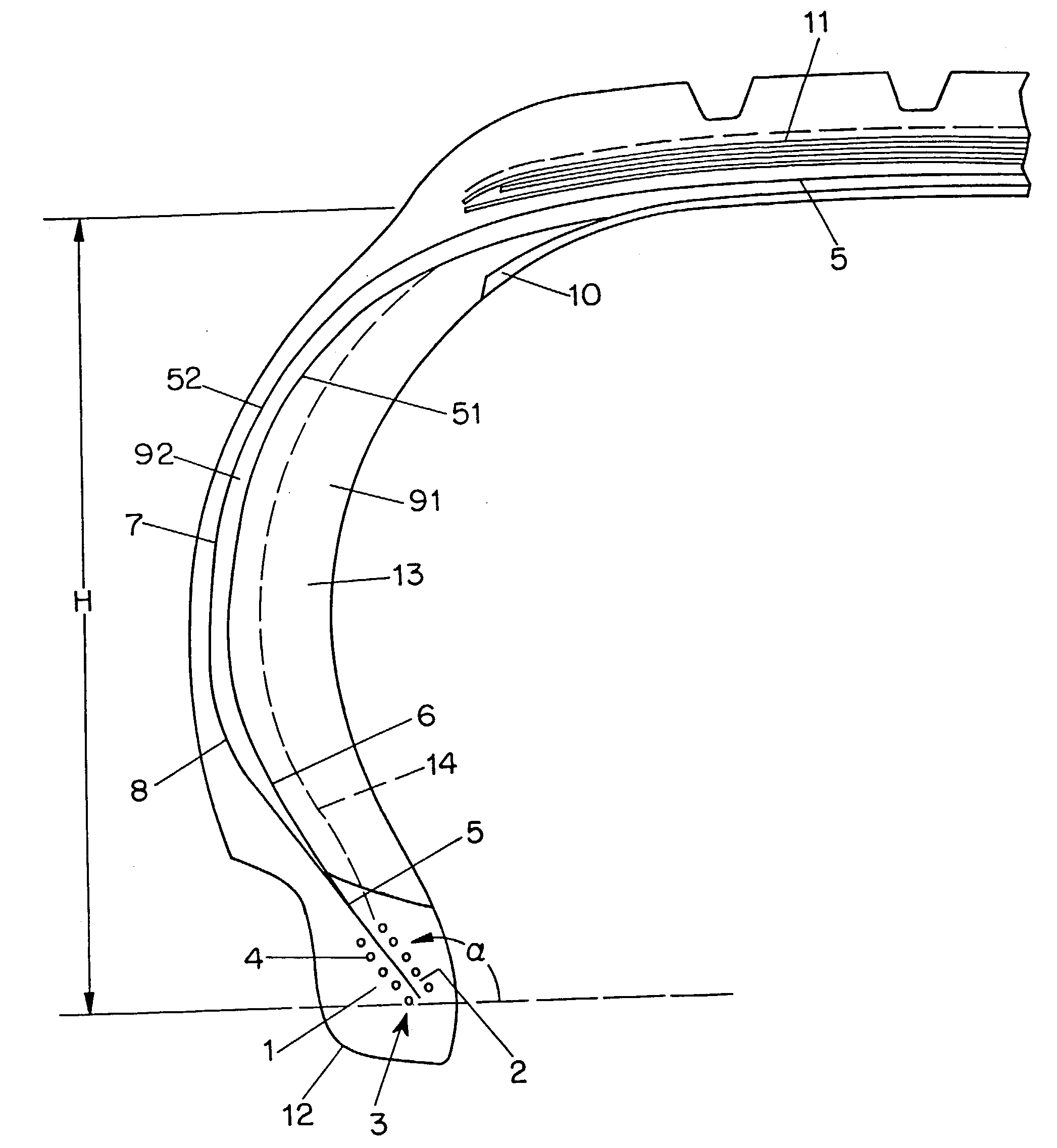
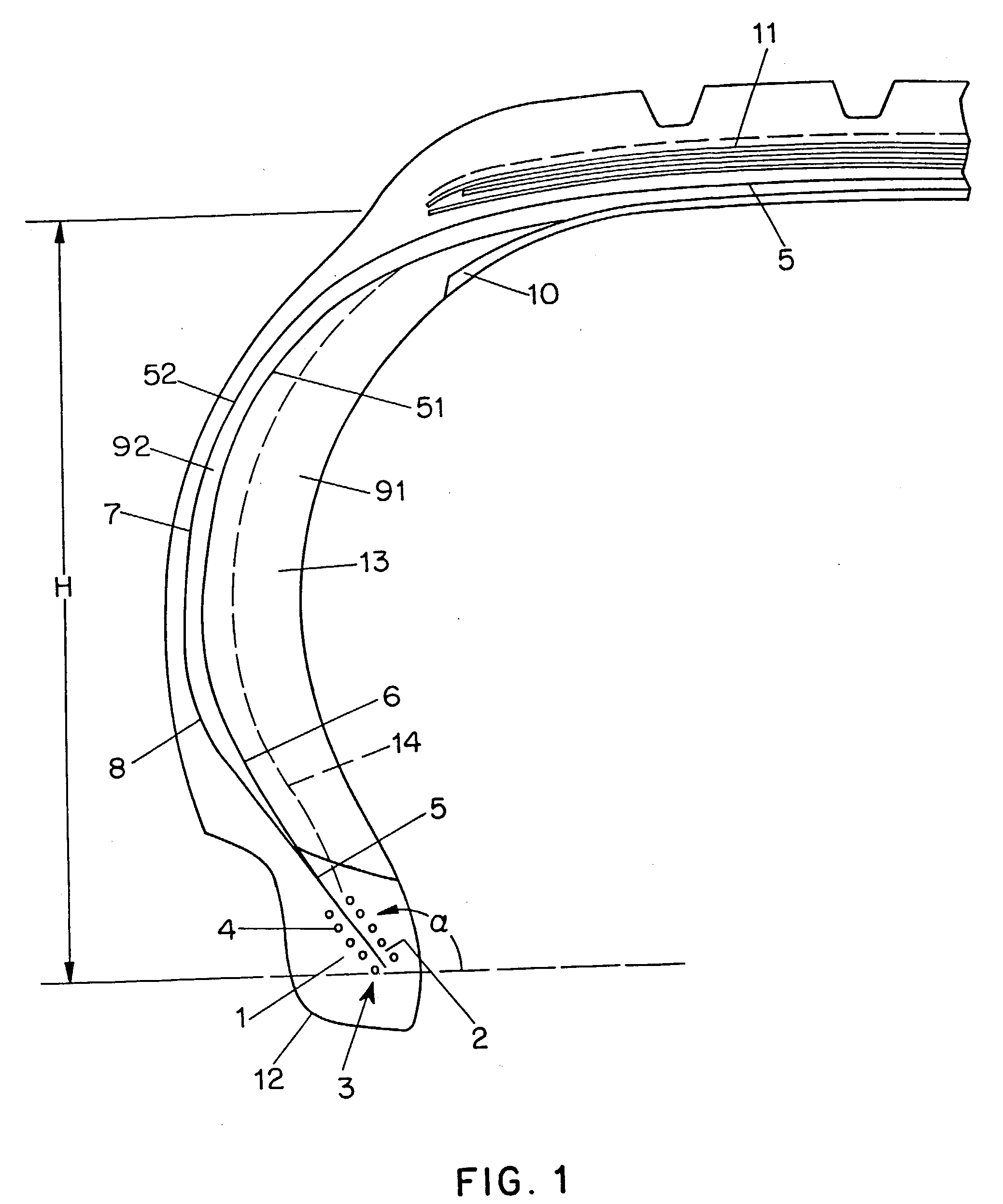
[0025]FIG. 1 illustrates the invention in which the carcass structure 5 has more than one carcass layer within some portion of the tire. The carcass structure 5 comprises one circumferential alignment of cords in the summit 11. In the sidewall portion 13 of the tire, the carcass structure 5 is divided in two circumferential alignments of radial cords 51 and 52. These two circumferential alignments of cords progressively diverge axially away from each other. In the bead 1, the two circumferential alignments of cords 51 and 52 join and give a common circumferential alignment of cords 5. Accordingly, in the bead 1, there is only one circumferential alignment of cords.

[0026] This carcass structure is very flexible and allows placing the carcass cords where they are most useful. For instance, the density of cords of the outer carcass layer 52 is advantageously superior to the carcass density of cords of the inner carcass layers 51. The cords of the outer carcass layer are subjected to hi...

second embodiment

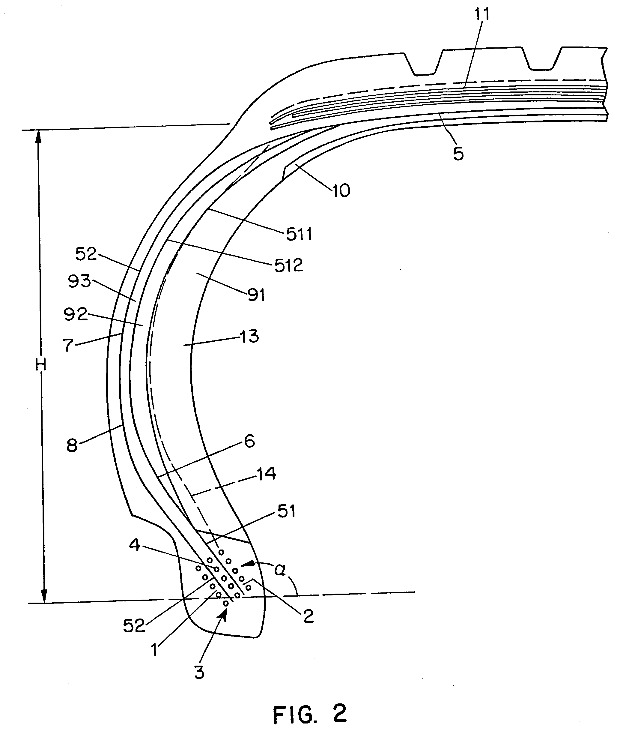
[0028]FIG. 2 illustrates the invention in which the carcass structure 5 comprises one circumferential alignment of cords in the summit 11. In the sidewall portion 13 of the tire, the carcass structure 5 is divided in three circumferential alignments of radial cords 511, 512 and 52. These three circumferential alignments of cords progressively diverge axially away from each other. In the bead 1, the two circumferential alignments of cords 511 and 512 join and give a common circumferential alignment of cords 51. Accordingly, in the bead 1, there are two circumferential alignments of cords 51 and 52.

[0029] The density of cords of carcass layer 52 is advantageously superior to the carcass density of cords of the carcass layers 511 and 512. This structure allows a limited thickness of the carcass structure in the summit and an appropriate anchoring in the bead portion. The anchoring of the carcass structure 5 is achieved by three windings 41, 42, 43 of circumferential oriented cords, whi...


PUM


Abstract

A tire is described having a carcass structure anchored in each side of the tire in a bead, a reinforced summit, and two sidewall portions joining the summit, each bead having a base, which is intended to be mounted on the tire's design mounting rim, and being extended radially upward by one of said sidewall portions, each bead further having an anchoring zone for anchoring the carcass in the bead, wherein the carcass structure has at least one circumferential alignment of cords in each bead anchoring zone which progressively divides in the respective sidewall portion in at least two circumferential alignments of cords, and wherein a runflat reinforcing member is disposed between the two carcass cord alignments and wherein the runflat reinforcing member is in direct contact with the cords of the two circumferential alignments.

Description

CROSS REFERENCE TO RELATED APPLICATIONS [0001] This application is a continuation of international PCT application Ser. No. PCT / EP01 / 11572, filed Oct. 8, 2001, which was published in English as WO 02 / 30691 on Apr. 18, 2002, which is a continuation of international PCT application Serial No. PCT / US00 / 27877, filed Oct. 10, 2000, which was published in English as WO 02 / 30691 on Apr. 18, 2002.BACKGROUND OF THE INVENTION [0002] The invention relates to a tire, more specifically to a pneumatic tire capable of continued mobility in a deflated condition. [0003] Various tire constructions have been proposed for pneumatic runflat tires; i.e., tires that normally operate in an inflated condition but which also permit a limited operation in a deflated condition. These tire constructions are generally formed of one or more generally radial carcasses which are turned up around one or more bead wires arranged in each bead, forming a wide curvilinear portion around the bead wires. The immediate con...

Claims


Application Information

Patent Timeline
IPC IPC(8): B60C9/08B60C15/00B60C15/06B60C17/00
CPCB60C15/0018B60C17/0009Y10T152/10855Y10T152/10846Y10T152/10819Y10T152/10828
Inventor COTTRELL, ROGER C.WILLARD, WALTER L. JR.
Owner MICHELIN RECH & TECH SA
Learn More