Liquid crystal display device

Active Publication Date: 2021-06-24
FUJIFILM CORP
View PDF0 Cites 1 Cited by
  • Summary
  • Abstract
  • Description
  • Claims
  • Application Information

AI Technical Summary

Benefits of technology

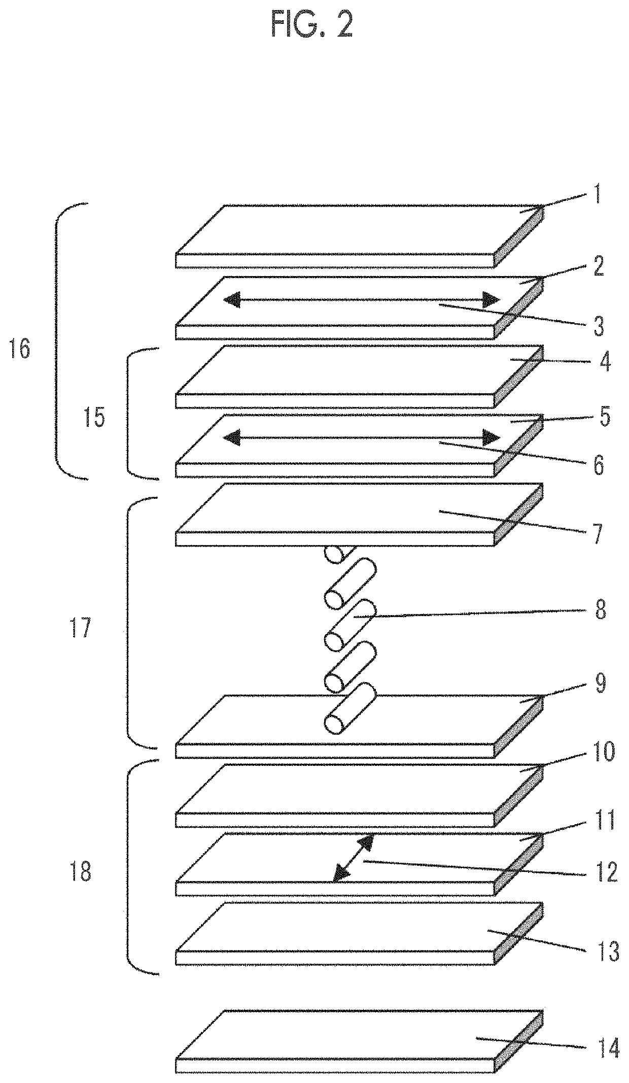
[0057](Protective Layer for Polarizer)
[0058]The protective layers 1, 10, and 13 for the polarizers are provided to protect the first polarizer 2 and the second polarizer 11.
[0059]The type of the protective layer is not particularly limited, and examples thereof include films such as cellulose acylate, polycarbonate, polysulfone, polyether sulfone, polyacrylate, polymethacrylate, cyclic polyolefin, polyolefin, polyamide, polystyrene, and polyester. Among these, a cellulose acylate film, a cyclic polyolefin film, a polyacrylate film, or a polymethacrylate film is preferable. Commercially available cellulose acetate films (for example, “TD80U” and “Z-TAC” manufactured by Fujifilm Corpora

Problems solved by technology

However, according to the study by the inventors, it has been found that in a case where the method described in JP2014-016642A is used, it is possible to reduce the light leak viewed from the oblique direction in the direction deviated from the absorption axis of the polarizer, but light leak viewed from an oblique direction in a direction of the absorption axis of the polarizer cannot be reduced at all.
Therefore, the viewing angle characteristics of the black display of the liquid crystal display device are not sufficiently improved by the method described in JP2014-016642A.
It has also been found that in the method described in JP2014-016642

Method used


Image

  • Liquid crystal display device
  • Liquid crystal display device
  • Liquid crystal display device

Examples


Example

[0184]The film thickness of the sample shown in Example 1 of JP2006-072309A was adjusted to produce an optically anisotropic layer 152.

[0185]The phase difference of the optically anisotropic layer 152 was measured by AxoScan, and the results were as follows: Re (550)=280 nm; Rth (550)=0 nm; Re (450) / Re (550)=1.00; and Re (550) / Re (650)=1.00.

[0186]The linear expansion coefficient of the optically anisotropic layer 152 in a slow axis direction was 73 ppm / ° C.

[0187]161>

[0188]A cellulose acetate film “TD80U” manufactured by Fujifilm Corporation was immersed in a 2.3 mol / L sodium hydroxide aqueous solution at 55° C. for 3 minutes. Next, the obtained film was washed in a water-washing bath at room temperature and neutralized using a 0.05 mol / L sulfuric acid at 30° C. The obtained film was washed again in the water-washing bath at room temperature, dried with warm air at 100° C., and saponified.

[0189]The TD80U saponified according to the above procedures, the polyvinyl alcohol-based polari...

Example

[0205]Next, a liquid crystal display device of Comparative Example 2 was produced in the same manner as in other examples, except that the second polarizing plate 181 (that is, a polarizing plate having no optically anisotropic layer) was attached to both sides of the liquid crystal cell 173.

[0206]

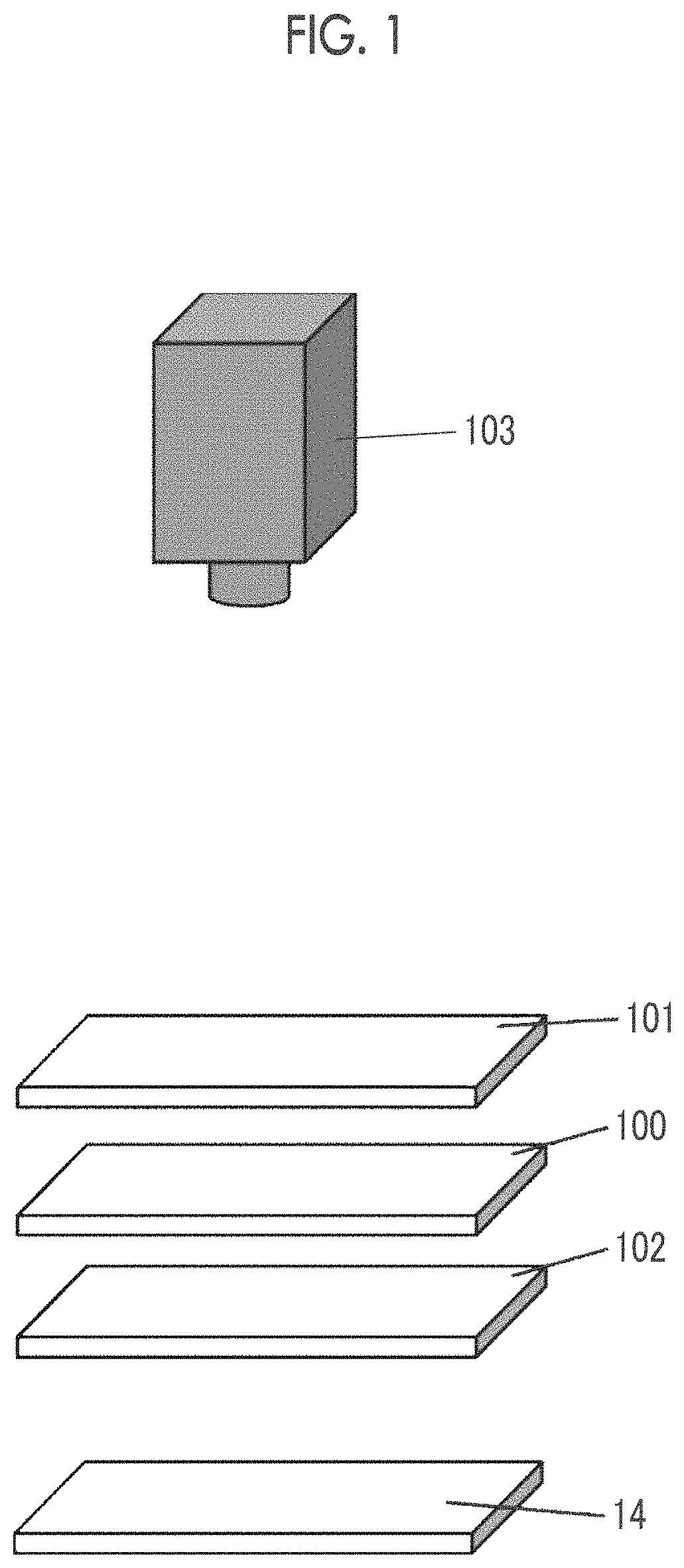
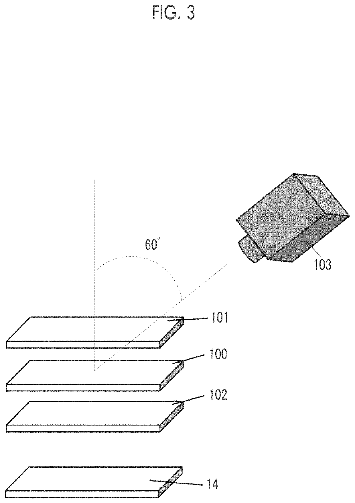
[0207]The produced liquid crystal display devices of the examples and the comparative examples were installed in a dark room, and the backlight was turned on in the absence of voltage application (that is, a black display state). The light leak of the liquid crystal display device in this state was measured using a spectral luminance meter SR-UL2 manufactured by Topcon Technohouse Corporation. In this case, the measurement by the spectral luminance meter was performed while adjusting the position and the angle so that an angle of 60° was formed from the vertical direction of the liquid crystal cell and an azimuthal angle was changed in increments of 15° in a range of 0° to 180° with respec...


PUM


Abstract

The present invention provides a liquid crystal display device which suppresses a color change of light leak depending on a direction in the visual recognition from an oblique direction during black display, and has high display quality. The liquid crystal display device includes, in order, at least: a first polarizer; an optically anisotropic layer a liquid crystal cell; and a second polarizer, the liquid crystal cell has pixels with a screen resolution of 250 ppi or more, the pixels each have at least blue, green, and red subpixels, the subpixel has a chevron structure in which an angle formed between at least one side and an absorption axis of the first polarizer or an absorption axis of the second polarizer is larger than 0° and not larger than 5°, and a depolarization degree of the liquid crystal cell in a visible light region satisfies a predetermined requirement.

Description

CROSS-REFERENCE TO RELATED APPLICATIONS[0001]This application is a Continuation of PCT International Application No. PCT / JP2019 / 035882 filed on Sep. 12, 2019, which claims priority under 35 U.S.C. § 119(a) to Japanese Patent Application No. 2018-170735 filed on Sep. 12, 2018 and Japanese Patent Application No. 2019-100243 filed on May 29, 2019. Each of the above applications is hereby expressly incorporated by reference, in its entirety, into the present application.BACKGROUND OF THE INVENTION1. Field of the Invention[0002]The present invention relates to a liquid crystal display device.2. Description of the Related Art[0003]In-plane switching (IPS) type liquid crystal display devices and fringe field switching (FFS) type liquid crystal display devices do not adopt a mode in which an electric field is applied between upper and lower substrates to make a rise of a liquid crystal compound, thereby achieving driving as in a twisted nematic (TN) type and vertical alignment (VA) type, bu...

Claims


Application Information

Patent Timeline
IPC IPC(8): G02F1/1335
CPCG02F1/133531G02F1/133514G02B5/30G02F1/133528G02F1/134372G02F1/134363
Inventor YAMADA, NAOYOSHIIWASAKI, TATSUYAOHMURO, KATSUFUMI
Owner FUJIFILM CORP
Why Eureka
Try Eureka