Belt band conveyor having separate guide shoes

a belt band and conveyor technology, applied in the direction of conveyors, conveyor parts, transportation and packaging, etc., can solve the problems of low friction wear, short life of guide strips, and failure of guide strips, which are known from the state of the art, after a correspondingly short period of use, and achieve even small deflections and high circulating speeds

Inactive Publication Date: 2005-04-21
INTERROLL HLDG
View PDF9 Cites 50 Cited by
  • Summary
  • Abstract
  • Description
  • Claims
  • Application Information

AI Technical Summary

Benefits of technology

[0013] The invention relates to a device for a belt band conveyor which allows for even small deflections and/or high circulating speeds. This result can occur wherein there can be a device with reliable guidance of the transport belt on the

Problems solved by technology

This occurs even in the case of a severely distorted curve, and in the case of significant level differences between the deflection rollers at the end, with low friction wear.
The stresses that occur have the result that the lifetime of the guide strips is short.
In the case of high speeds and small deflections, such guide strips, known from the state of the art, fail after a correspondingly short period of use.
With these solution variants, however, permanent excess stress in the region of the roll

Method used


Image

  • Belt band conveyor having separate guide shoes
  • Belt band conveyor having separate guide shoes
  • Belt band conveyor having separate guide shoes

Examples


Embodiment Construction

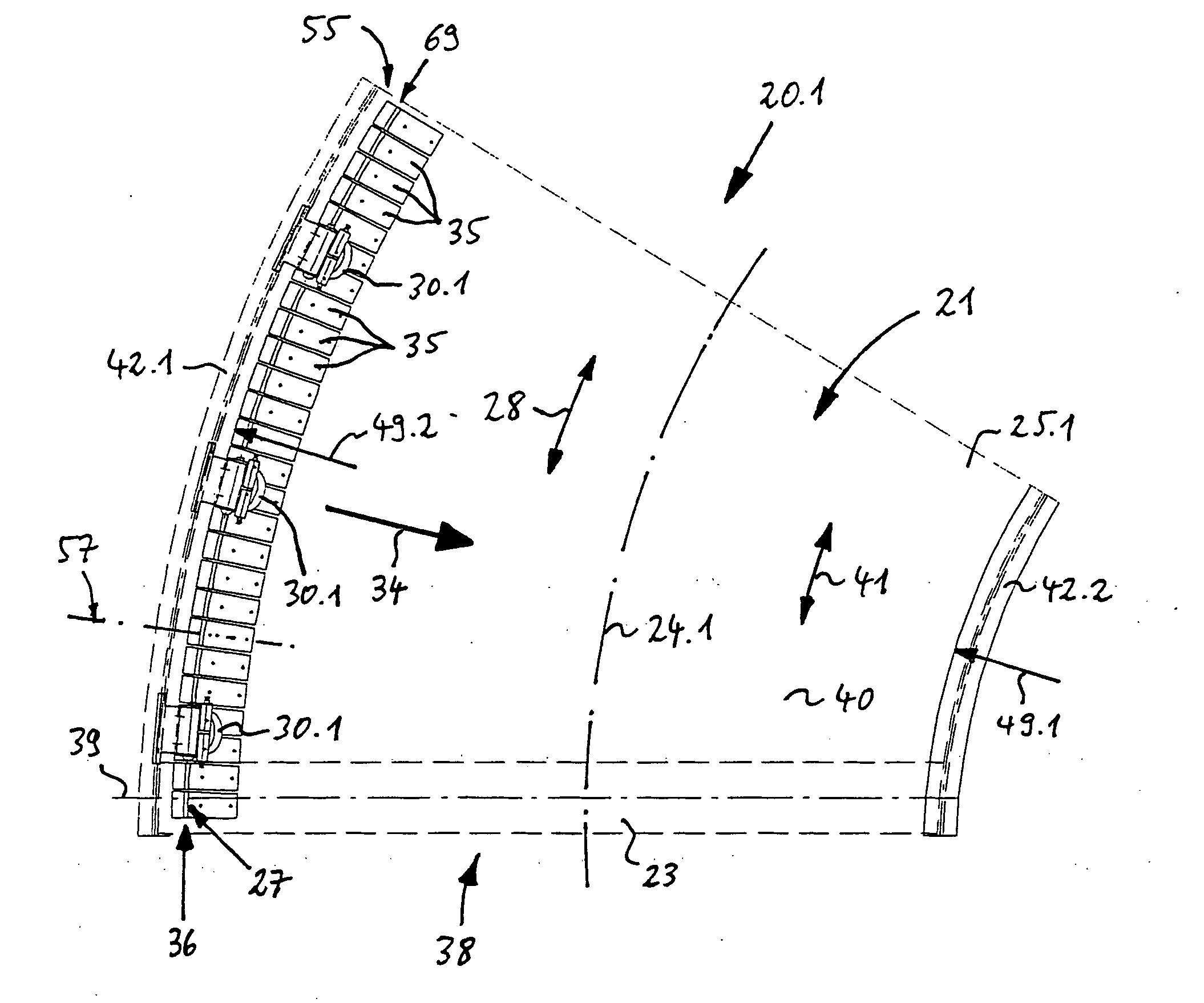
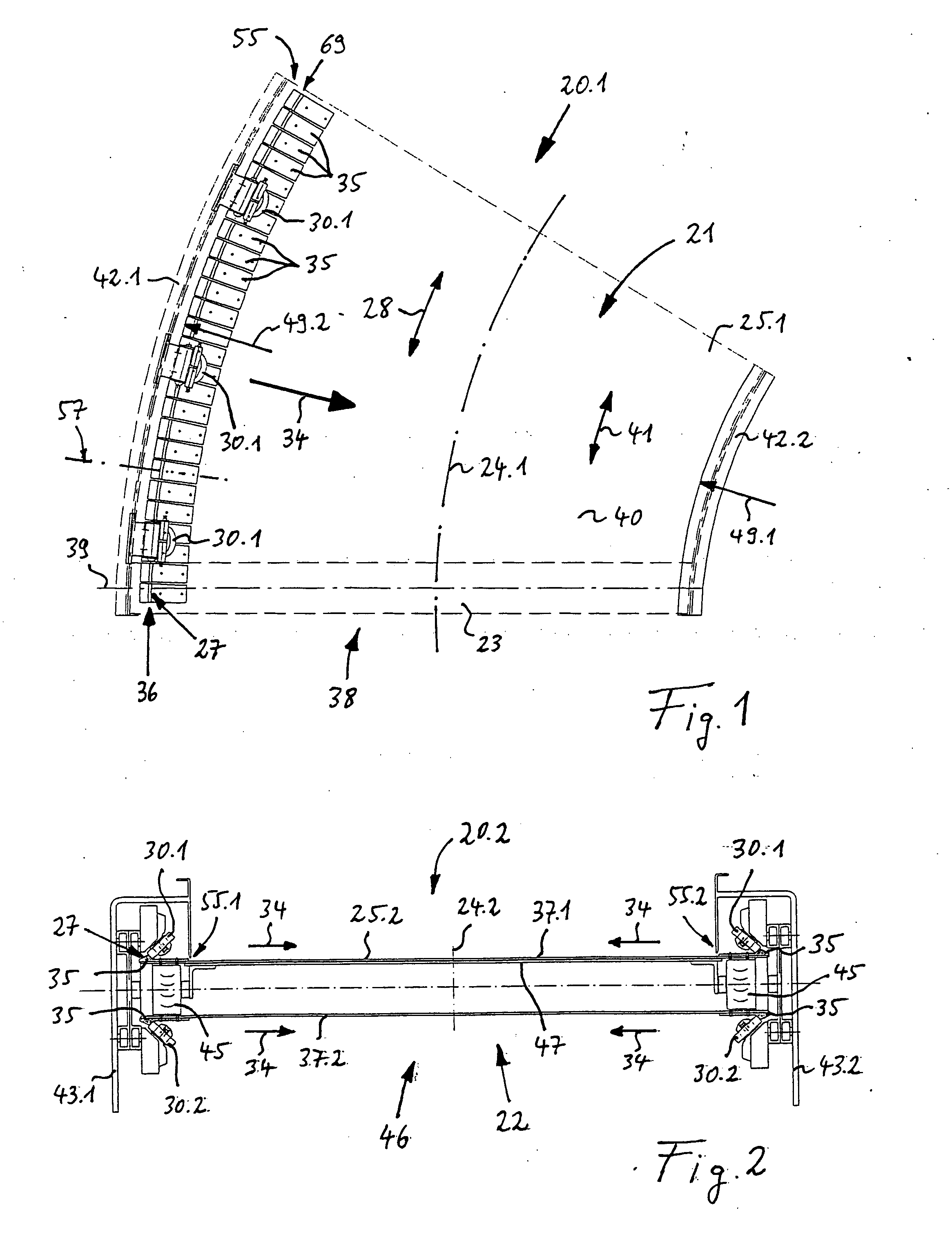
[0038] Referring to the drawings, FIG. 1 shows a belt band conveyor 20.1 configured as a curved belt conveyor 21. This curved belt conveyor has a transport segment 41 of a belt curve 38 that extends over a circular ring sector 40, which is formed by a closed, endless, band-shaped transport belt 25.1. Belt 25.1 can be guided by way of deflection rollers 23 that are rotatable around a rotation axis 39 and arranged at both ends of a circular ring sector 40, in each instance. Belt 25.1 is also guided by running rollers 30.1 that are arranged at uniform angular distances between them, which are not shown in FIG. 1. The axes of the running rollers intersect in a center of the circular ring sector 40, in a center point.

[0039] Running rollers 30.1 can be rollers that rise conically from an inside radius 49.1 of belt curve 38 to an outside radius 49.2 of belt curve 38, or cylindrical rollers. Deflection rollers 23 and / or the running rollers 30.1 can be formed, in each instance, from roller ...


PUM


Abstract

The invention relates to a belt band conveyor such as a curved belt conveyor having an endless transport belt that is guided over deflection rollers. There is a guide element that projects beyond the belt plane wherein this guide element can be handled separately before it is attached to the transport belt. This guide element moves along as the transport belt moves, and on whose guide surfaces, which extend in the transport direction of the transport belt has running surfaces that are inclined relative to the belt plane roll off from rotating guide rollers as the transport belt moves. Thus, lateral forces that occur crosswise to the transport direction of the transport belt can be compensated. A plurality of separate guide shoes are attached to the transport belt, forming a guide strip for the guide rollers that extends in the transport direction, circulates, and is divided into multiple parts.

Description

CROSS REFERENCE TO RELATED APPLICATIONS [0001] This Application claims priority under 35 U.S.C. 119 from German Application Serial No. 103 49 049.3-22 filed on Oct. 17, 2003. BACKGROUND OF THE INVENTION [0002] The invention relates to a belt band conveyor, particularly a curved belt conveyor, having an endless transport belt that is guided over deflection rollers. Attached to the transport belts, is a guide element that projects beyond the belt plane. This guide element can be handled separately before it is attached to the transport belt, and which moves along as the transport belt moves. The guide element has guide surfaces, which extend in the transport direction of the transport belt. There are also running surfaces that are inclined relative to the belt plane and which roll off from rotating guide rollers, to compensate for lateral forces that occur crosswise to the transport direction of the transport belt. [0003] A curved belt conveyor has become known from German Patent DE 4...

Claims


Application Information

Patent Timeline
IPC IPC(8): B65G15/02B65G15/60
CPCB65G15/60B65G15/02
Inventor AXMANN, NORBERT
Owner INTERROLL HLDG
Why Eureka
Try Eureka