
Telescoping column having rake spring assist

a technology of telescopic column and spring assist, which is applied in the direction of steering column, steering parts, vehicle components, etc., can solve the problem of large percentage of the full capacity of the rake, and achieve the effect of minimal effort and little change in effor

Inactive Publication Date: 2005-08-02
STEERING SOLUTIONS IP HLDG +1
View PDF10 Cites 5 Cited by
  • Summary
  • Abstract
  • Description
  • Claims
  • Application Information

AI Technical Summary

Benefits of technology

[0008]The invention has the advantage of orienting the spring assist about the rake pivot axis such that the spring provides a constant or nearly constant assist force through supporting the column relative to the support member, such that the operator of the vehicle experiences very little change in the effort required to position the column in different rake angles throughout the full travel of the rake adjustment. Preferably, the torsion spring provides a near equilibrium support to the steering column throughout its full rake travel, such that a very minimal effort is required on the part of the operator to move the column between the positions and, once positioned, the torsion spring supports the column unassisted in the desired position of adjustment.
[0009]The invention has the further advantage of isolating the reaction of the torsion spring of the rake adjust from telescopically adjustable upper and lower column jackets of a column assembly. According to a preferred feature of the invention, the torsion spring is carried on the lower jacket which is stationary relative to the telescoping upper jacket. The torsion spring reacts between the lower column jacket and the support member during rake adjustment without direct engagement with the upper column jacket, and as such does not produce any drag or interference to the telescoping action of the column assembly.
[0010]Another advantage of the present invention is that the position of the torsion spring relative to the axis provides full range of support to the column during its rake adjustment with a corresponding small deflection of the torsion spring, eliminating large variations and rake effort due to large deflections of the spring. As such, the small range of movement of the torsion spring enables the designer of rake adjust columns to select a spring which provides equilibrium or near equilibrium support of the column in any one position, which changes very little over the full range of rake movement of the column compared with the comparably small deflection of the torsion spring. In this way, a near equilibrium support of the column is maintained throughout its full rake adjust travel.

Problems solved by technology

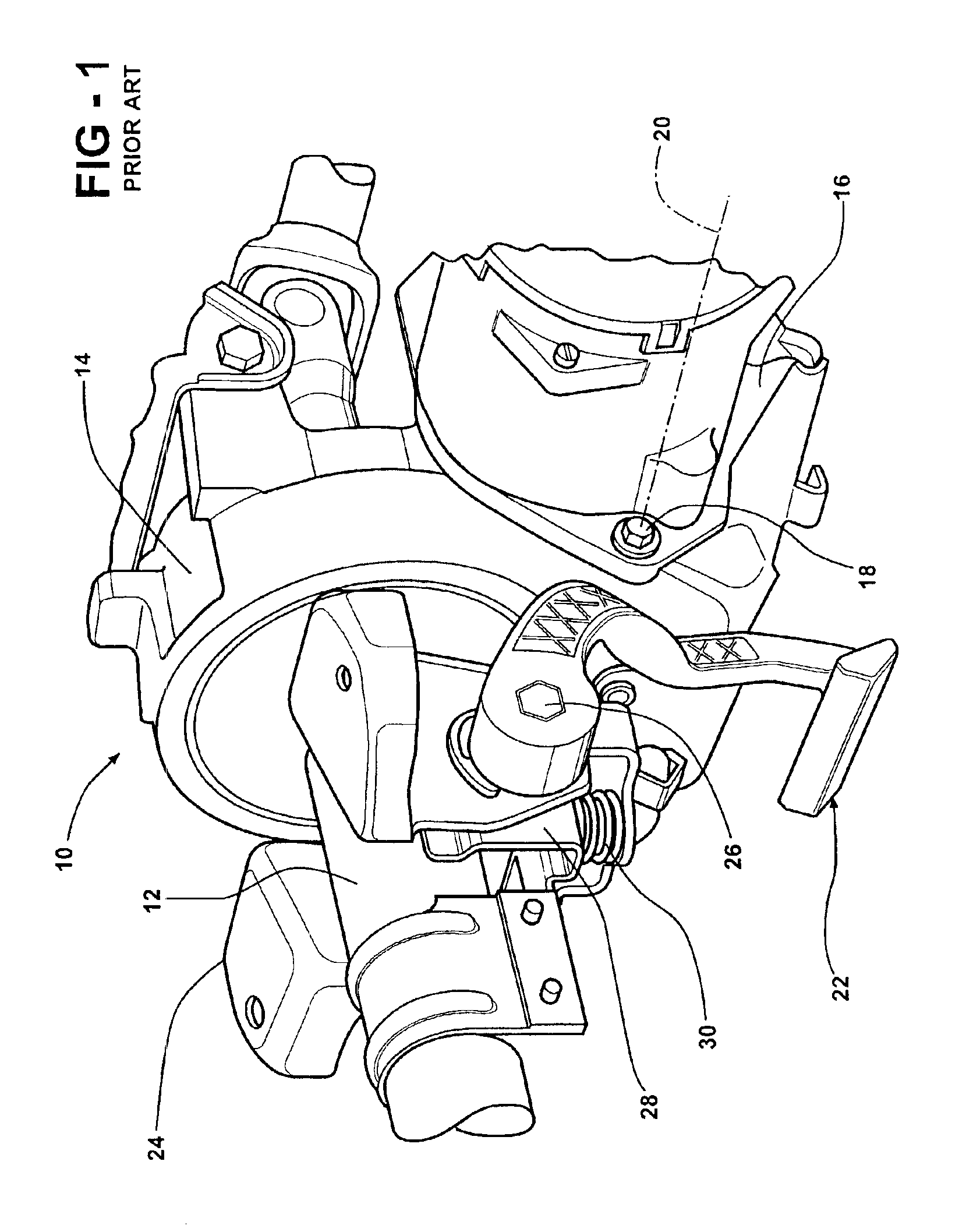
Due to packaging and position the springs will have to deflect a large percentage of its full capacity.

Method used


Image

  • Telescoping column having rake spring assist
  • Telescoping column having rake spring assist
  • Telescoping column having rake spring assist

Examples


Embodiment Construction

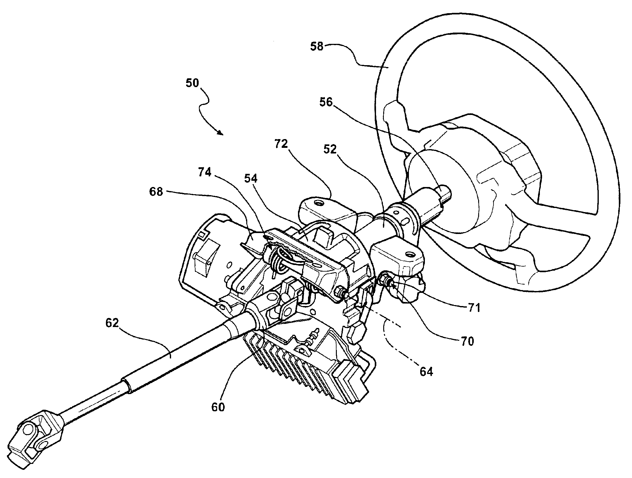
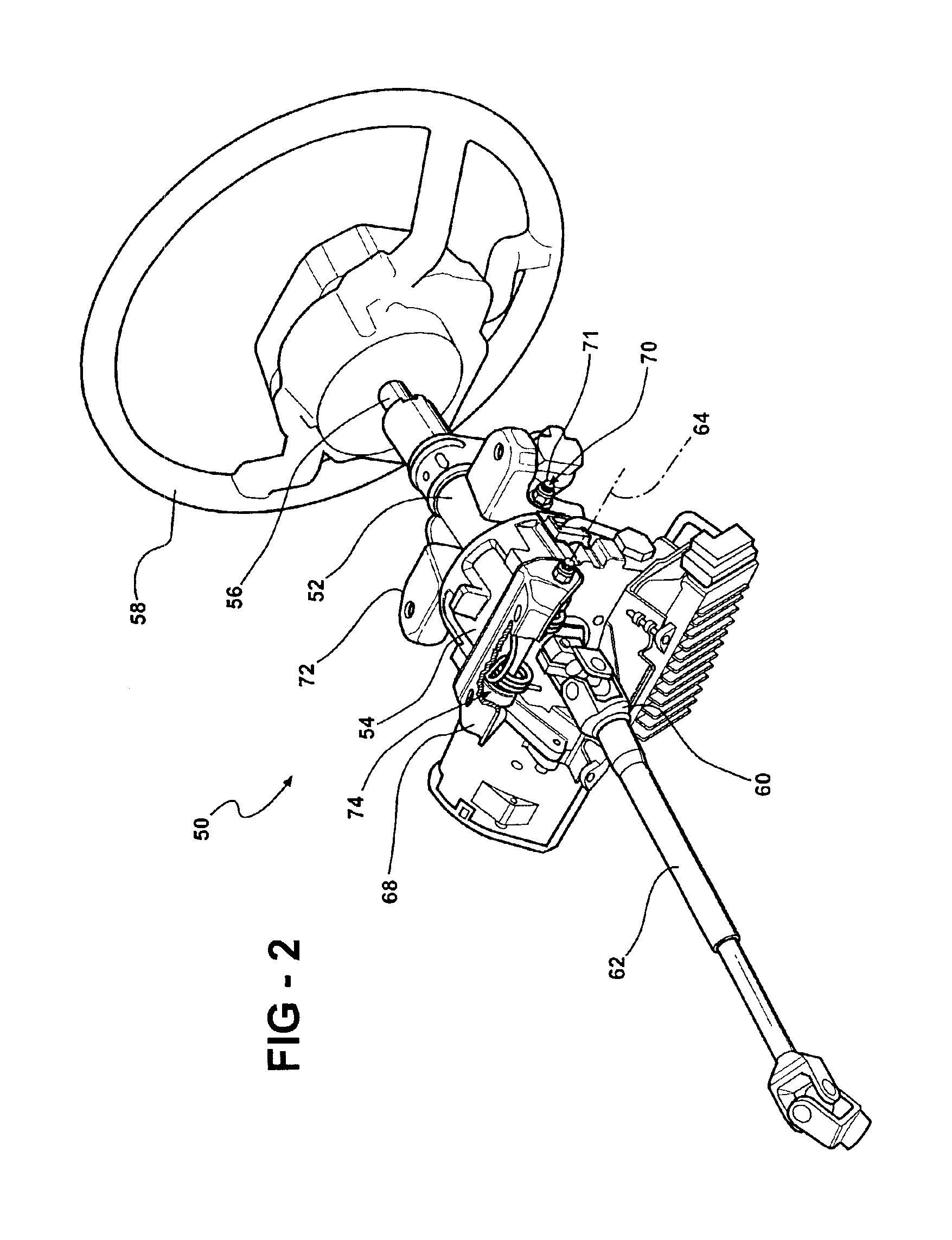
[0017]Turning now to FIGS. 2-4, a column assembly 50 constructed according to a presently preferred embodiment of the invention is shown having an upper column jacket 52 which is supported for telescoping movement in the direction of its length relative to an axially stationary lower column jacket 54. An upper steering shaft 56 extends through the column jackets 52, 54 between an upper end on which a hand control 58 (e.g., a steering wheel) is mounted and a lower end coupled by a universal joint 60 to an intermediate steering shaft 62. The column jackets 52,54 and upper shaft 56 are supported for pivotal movement about an axis 64 of a pivot bolt 66 which extends transversely of the column jackets 52,54 and is supported by a stationary mounting bracket 68 fixed to stationary support structure of a vehicle. The column assembly 50 is thus able to pivot up and down about the axis 64 of the pivot bolt 66 to enable an operator to adjust the up and down tilt or rake of the column 50 to a d...


PUM


Abstract

A steering column assembly for a vehicle includes a steering column for operatively mounting a hand controller used for controlling the steering of the vehicle. A support member is disposed adjacent the steering column and is coupled thereto by a rake pivot connection which enables the steering column to pivot about an axis of the rake pivot connection relative to the support member along a rake adjustment path for adjusting a rake position of the steering column. A torsion spring is disposed about the axis between the steering column and the support member to provide a constant spring bias force therebetween. The torsion spring preferably provides near-equilibrium support of the column through its full rake adjust travel. The torsion spring further is readily adaptable to telescopic-type columns and does not interfere with the telescopic adjustment.

Description

[0001]This application claims the benefit of U.S. Provisional Application No. 60 / 363,196, filed Mar. 11, 2002.TECHNICAL FIELD[0002]This invention relates generally to automotive steering columns, and more particularly to those having rake adjust.BACKGROUND OF THE INVENTION[0003]Steering columns for automotive vehicles are often equipped with various adjustments that enable the operator of the vehicle to position and lock the column in any of a number of positions. Some columns includes brake and telescope adjustment to enable the operator to adjust the angle of the column as well as the fore and aft telescope position of the hand wheel.[0004]Current designs are using compression springs, torsion springs or a bending leaf spring which applies the load in the area of the rake mechanism. Due to packaging and position the springs will have to deflect a large percentage of its full capacity. Therefore, the spring force varies greatly. The driver experiences a change of rake effort when g...

Claims


Application Information

Patent Timeline
IPC IPC(8): B62D1/18B62D1/187
CPCB62D1/187
Inventor RYNE, PATRIK M.GERDING, CHAD E.KNIEBBE, BRUCE D.
Owner STEERING SOLUTIONS IP HLDG
Learn More