Agricultural working machine

a working machine and agri-industrial technology, applied in the direction of mechanical control devices, manual control with single controlling member, instruments, etc., can solve the problems of inability to adjust the working tool, damage to the working tool, and high repair costs, so as to prevent inadvertent and prevent small deflection of the control element.

Inactive Publication Date: 2013-08-15
CLAAS SELBSTFAHRENDE ERNTEMASCHINEN GMBH
View PDF11 Cites 5 Cited by
  • Summary
  • Abstract
  • Description
  • Claims
  • Application Information

AI Technical Summary

Benefits of technology

[0008]In an embodiment, the invention provides an agricultural working tool that permits working tools to be handled rapidly as well as safely.
[0018]The position of the working tool being influenced by accidental, small deflections of the control element also can be prevented in that an interval of the deflection, in which the speed of the working tool is zero, extends on either side of the neutral position. The tool, therefore, does not begin to move until the control element is deflected out of said interval.

Problems solved by technology

The raising and lowering of a working tool requires a great deal of caution and practice on the part of a user.
Mistakes can result in damage to the working tool, which are costly to repair.

Method used


Image

  • Agricultural working machine
  • Agricultural working machine
  • Agricultural working machine

Examples


Embodiment Construction

[0027]The following is a detailed description of example embodiments of the invention depicted in the accompanying drawing. The example embodiments are presented in such detail as to clearly communicate the invention and are designed to make such embodiments obvious to a person of ordinary skill in the art. However, the amount of detail offered is not intended to limit the anticipated variations of embodiments; on the contrary, the intention is to cover all modifications, equivalents, and alternatives falling within the spirit and scope of the present invention, as defined by the appended claims.

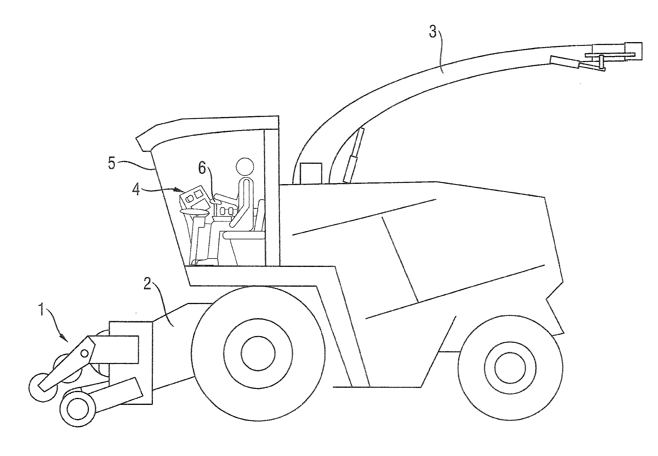
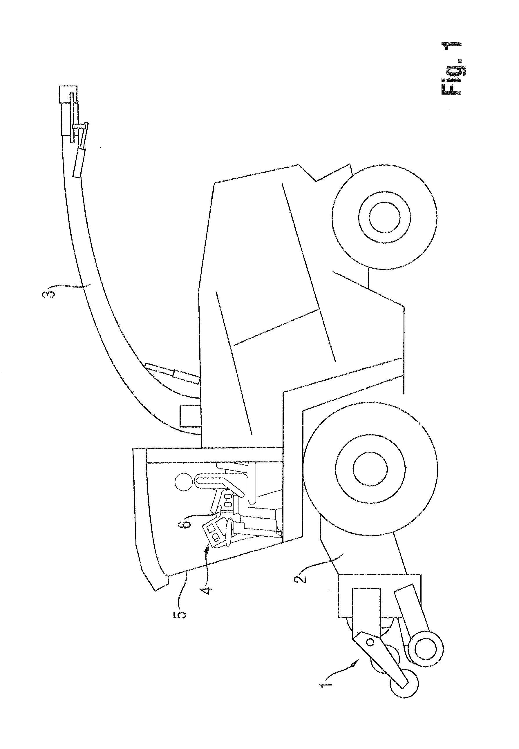
[0028]A person skilled in the art is familiar with the basic features of the forage harvester, such as the forest harvester depicted in FIG. 1. Hence, this disclosure does not describe in detail known assemblies used in conventional harvesting machines, such as front harvesting attachment 1, intake assembly 2, chopping mechanism, and transfer bend 3. What is important for an understanding of...


PUM


Abstract

An agricultural working vehicle includes a working tool, a drive assembly for raising and lowering the working tool and a control element that is deflected from a neutral position in different directions. A speed (v) at which the drive assembly moves the working tool is a continuous function of a deflection (a) of the control element.

Description

CROSS-REFERENCE TO A RELATED APPLICATION[0001]The invention described and claimed hereinbelow is also described in German Patent Application DE 10 2012 002992.6, filed on Feb. 15, 2012. This German Patent Application, subject matter of which is incorporated herein by reference, provides the basis for a claim of priority of invention under 35 U.S.C. 119(a)-(d).BACKGROUND OF THE INVENTION[0002]The invention broadly relates to an agricultural working vehicle such as a forage harvester or a combine harvester.[0003]The working tools of conventional agricultural working vehicles such as forage or combine harvesters are generally removable, whether to replace the working tool in order to adapt to work to be performed or because the dimensions of the working tool are so great that the working vehicle, with the working tool mounted thereon, is prohibited from traveling on public roads. In that case, the working tool must be delivered separately, e.g., on a trailer drawn by the working vehicl...

Claims


Application Information

Patent Timeline
Patent Type & Authority Applications(United States)
IPC IPC(8): G05G1/04
CPCA01D43/08E02F9/2004Y10T74/20396G05G9/047G05G2009/04774G05G1/04
Inventor SCHWENK, INGOHARENKAMP, HENNING
Owner CLAAS SELBSTFAHRENDE ERNTEMASCHINEN GMBH
Why Eureka
Try Eureka