Connector locking construction

a technology of connecting rods and locking rods, applied in the direction of coupling device connections, mechanical devices, fastening means, etc., can solve the problems of poor locking strength and often not generated sufficient lock feeling, and achieve the effect of reducing the return force of the lock arm, stable lock feeling, and secure clicking feeling

Inactive Publication Date: 2005-04-21
SUMITOMO WIRING SYST LTD
View PDF7 Cites 27 Cited by
  • Summary
  • Abstract
  • Description
  • Claims
  • Application Information

AI Technical Summary

Benefits of technology

[0012] In an alternate design, the leading end of the lock arm is formed into a frame that surrounds the one end of the unlocking arm. The unlocking portion is formed on each of the left and right edges of the unlocking arm for engaging the back surface of corresponding frame pieces at the leading end of the lock arm. With this construction, the lock can be wider than the lock arm. Thus, a large area of engagement can be ensured with the engaging portion of the mating housing to enhance the locking strength.
[0013] The locking end of the lock arm may extend back with respect to a connecting direction with the first housing, and the unlocking end of the unlocking arm may extend forward with respect to the connecting direction with the mating housing for abutment against the locking end of the lock arm. Thus, the lock arm can successively move onto the engaging portion of the first housing from the base end towards the leading end as the two housings are connected. Thus, a counteracting force from the lock arm gradually decreases as the connection progresses, and the connecting operation can be carried out smoothly with less feeling of resistance.
[0014] As described above, the unlocking arm is an inclinable seesaw separate from the lock arm and the lock of the lock arm is pushed up to cancel the locked state by utilizing the lever action of the unlocking arm. Thus, unlocking is carried out smoothly and securely while increasing the locking force by thickening the base end of the lock arm to enhance the rigidity thereof. A fulcrum of the unlocking arm can be narrowed to a necessary and minimum extent so that the unlocking arm can be inclined with a small force. Accordingly, both an increase in the locking strength and a reduction in the unlocking force can be realized.
[0016] In contrast, the leading end of the lock arm and the one end of the unlocking arm are separate according to the present invention. Thus, only the lock arm is inclined as the two housings are connected, and only the lock arm returns when the two housings are properly connected. Therefore, the lock can hit the upper surface of the mating connector housing with force, thereby giving a loud hitting source and a secure clicking feeling.
[0017] The lock arm is cantilevered. Thus, a reduction in a returning force of the lock arm due to contact of a finger or other part with an end of the lock arm opposite the lock is avoided. This also contributes to a stable lock feeling.

Problems solved by technology

Conversely, efforts to reduce the unlocking force result in a poor locking strength.
Thus, a sufficient lock feeling often is not generated.

Method used


Image

  • Connector locking construction
  • Connector locking construction
  • Connector locking construction

Examples


first embodiment

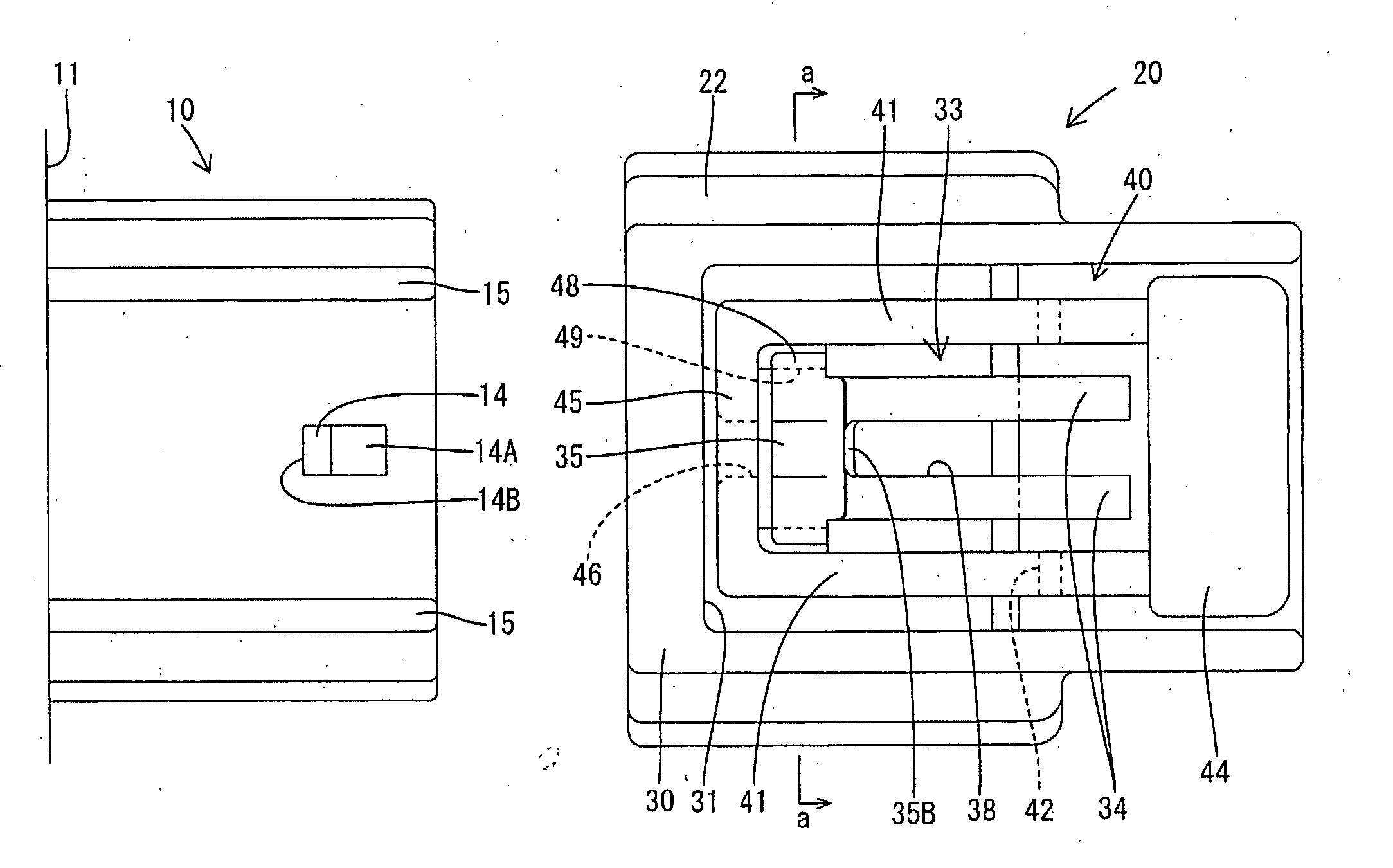
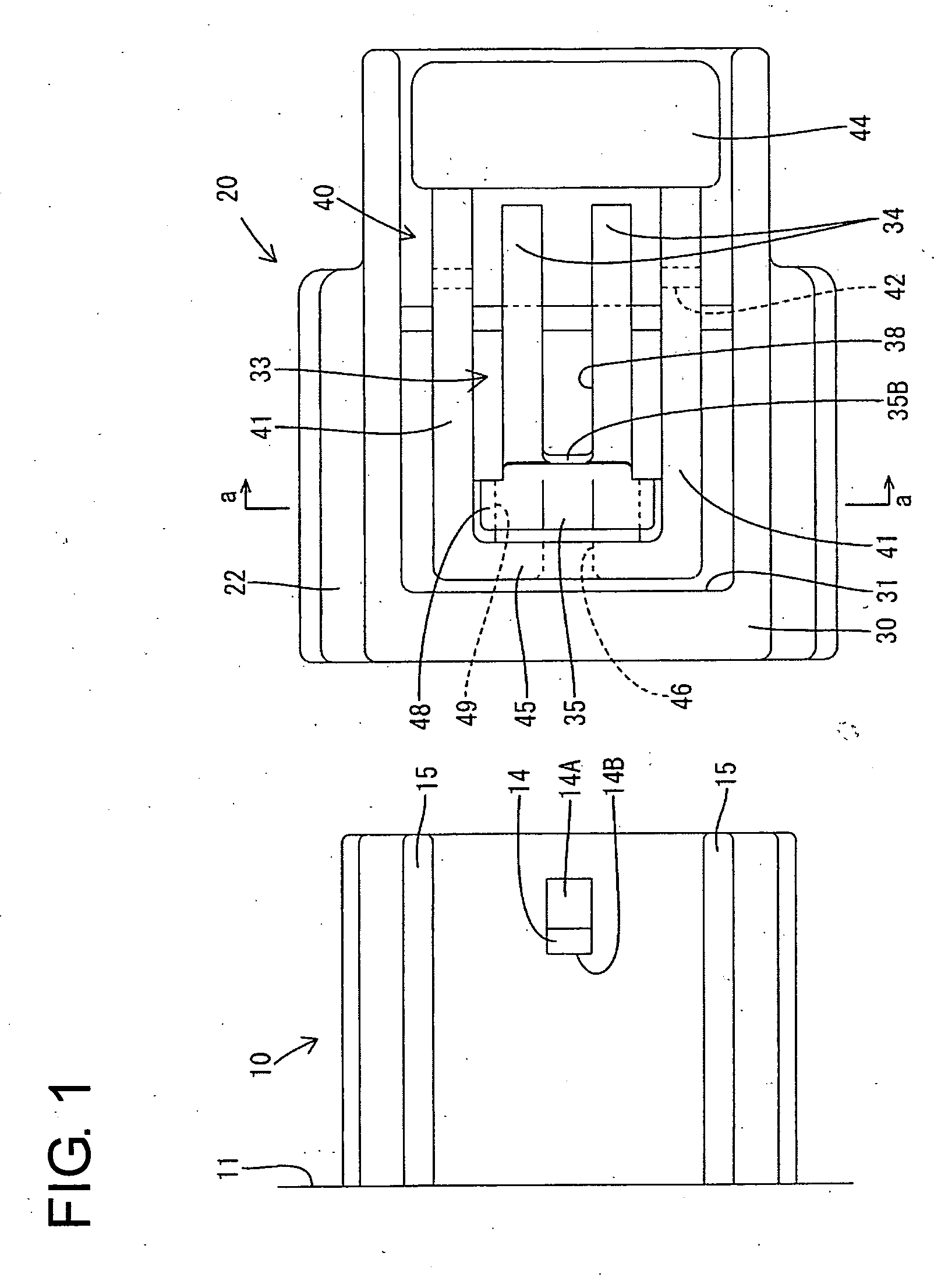
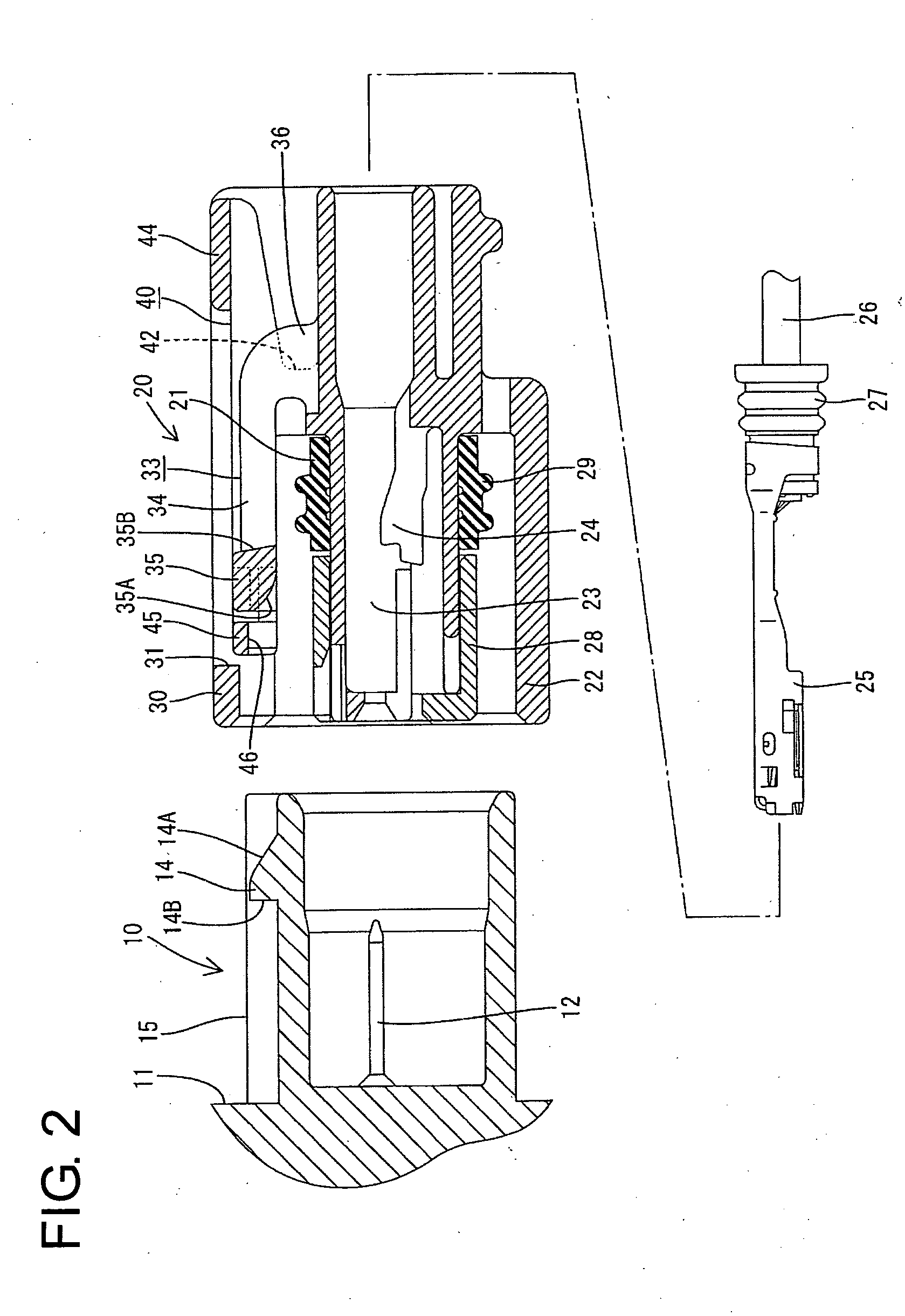
[0054] a connector according to the invention is described with reference to FIGS. 1 to 12. The connector is comprised of a male housing 10 and a female housing 20 connectable with each other, as shown in FIGS. 1 and 2. In the following description, ends of the respective housings 10, 20 to be connected are referred to as the front.

[0055] The male housing 10 is coupled directly to an apparatus and is a wide tube that projects integrally from an outer wall of an apparatus main body 11 made of a synthetic resin, as shown in FIG. 3. Three tab-shaped male terminals 12 project side-by-side at specified intervals along a transverse direction from the back surface of the male housing 10.

[0056] An engaging portion 14 projects from the widthwise center of the upper surface of the male housing 10 close to the front end. A slanted guiding surface 14A is defined at the front of the engaging portion 14 and a vertical engaging surface 14B is defined at the rear surface thereof.

[0057] Guide wall...

third embodiment

[0098] In the third embodiment as well, the unlocking arm 80 can be inclined like a seesaw and is provided separately from the lock arm 73. The lock 75 of the lock arm 73 is pushed up by the lever action generated by inclining the unlocking arm 80, thereby canceling the locked state. Thus, unlocking can be carried out smoothly and securely while increasing the locking force by the relatively short lock arm 73 that extends directly from the front edge of the window hole 31 B of the arched portion 30 to enhance the rigidity. The unlocking arm 80 can be inclined with a small force by narrowing the fulcrum portion 82 of the unlocking arm 80 to a necessary and minimum extent.

[0099] The lock 75 of the lock arm 73 and the front end of the unlocking arm 80 are separate. Thus, only the lock arm 73 is inclined as the two housings 10B, 20B are connected and only the lock arm 73 returns when the two housings 10B, 20B are connected properly. The lock 75 can hit the upper surface of the mating ma...


PUM


Abstract

A lock (35) is provided at the leading end of a resiliently deformable lock arm (33) on a female housing (20) and engages an engaging portion (14) on a male housing (10). An unlocking arm (40) is provided separate from the lock arm (33) and is resiliently inclinable like a seesaw. Projecting pieces (48) are formed on opposite surfaces of the lock (35) and unlocking pieces (49) on the unlocking arm (40) face the backsides of the projecting pieces (48). An operable portion (44) of the unlocking arm (40) is pressed to incline the unlocking arm (40) so that the unlocking pieces (49) lift the lock (35) of the lock arm (33), thereby canceling a locked state.

Description

BACKGROUND OF THE INVENTION [0001] 1. Field of the Invention [0002] The present invention relates to a connector locking construction. [0003] 2. Description of the Related Art [0004] U.S. Pat. No. 5,713,761 and FIG. 36 herein disclose a locking construction for a connector. With reference to FIG. 36, the connector has a female housing 1 with a lock arm 2 that can undergo a seesaw-like resilient deformation. The connector also has a male housing 3 with an engaging portion 4 that is engageable with a lock 5 at the front end of the lock arm 2. An operable portion 6 is provided at the rear end of the lock arm 2. The lock 5 moves onto the engaging portion 4 at an intermediate stage of a connecting operation of the female and male housings 1, 3. Thus, the lock arm 2 resiliently inclines about a fulcrum 7. The lock 5 passes the engaging portion 4 when the housings 1, 3 are connected properly. Thus, the lock arm 2 returns to its initial position so that the lock 5 engages the rear surface o...

Claims


Application Information

Patent Timeline
Patent Type & Authority Applications(United States)
IPC IPC(8): H01R13/639E05C5/00H01R13/50H01R13/52H01R13/627H01R13/641
CPCH01R13/50H01R13/633H01R13/6272H01R13/5219Y10T292/089
Inventor ICHIDA, KIYOFUMIFUKATSU, YUKIHIROTOYODA, YUKIHIROOKAYASU, YASUSHI
Owner SUMITOMO WIRING SYST LTD
Why Eureka
Try Eureka