Plasma display panel

a technology of display panel and plasma, which is applied in the direction of static indicating devices, instruments, and address electrodes, etc., can solve the problems of limiting any attempts to make more effective use of the substrate, the degree to which the display region may be increased, and the length of the second segment may increase, so as to reduce the distance from the center of the second segment is increased, and the length of the second segment increases.

Inactive Publication Date: 2005-04-21
SAMSUNG SDI CO LTD
View PDF8 Cites 12 Cited by
  • Summary
  • Abstract
  • Description
  • Claims
  • Application Information

AI Technical Summary

Problems solved by technology

In addition, short circuits may occur in electrodes 2 because of poor shapes of manufactured segments 9, 11.
Hence, the conventional structure places limitations on the degree to which the display region may be increased relative to the terminal region.
Stated differently, there are limits to any attempts at making more effective use of the substrate.
Furthermore, there are also restrictions with respect to increasing the number of electrodes in an effort to improve picture quality.

Method used


Image

  • Plasma display panel
  • Plasma display panel
  • Plasma display panel

Examples


Embodiment Construction

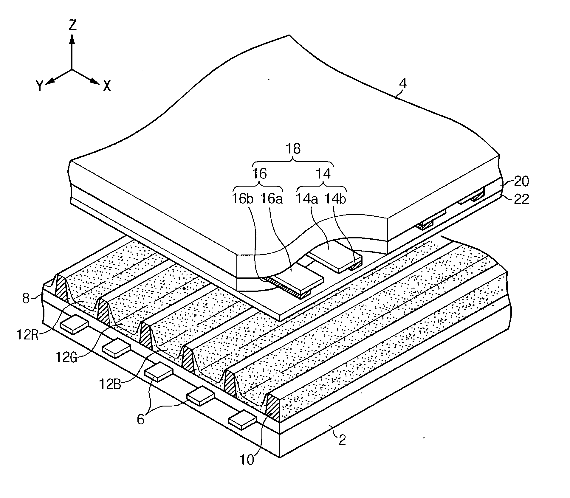
[0035] Referring first to FIG. 3, a PDP according to an exemplary embodiment of the present invention includes first substrate 2 and second substrate 4 provided opposing one another with a predetermined gap therebetween. Discharge cells are formed in the gap between first substrate 2 and second substrate 4. An independent discharge mechanism of each of the discharge cells functions to emit visible light to thereby realize the display of predetermined color images.

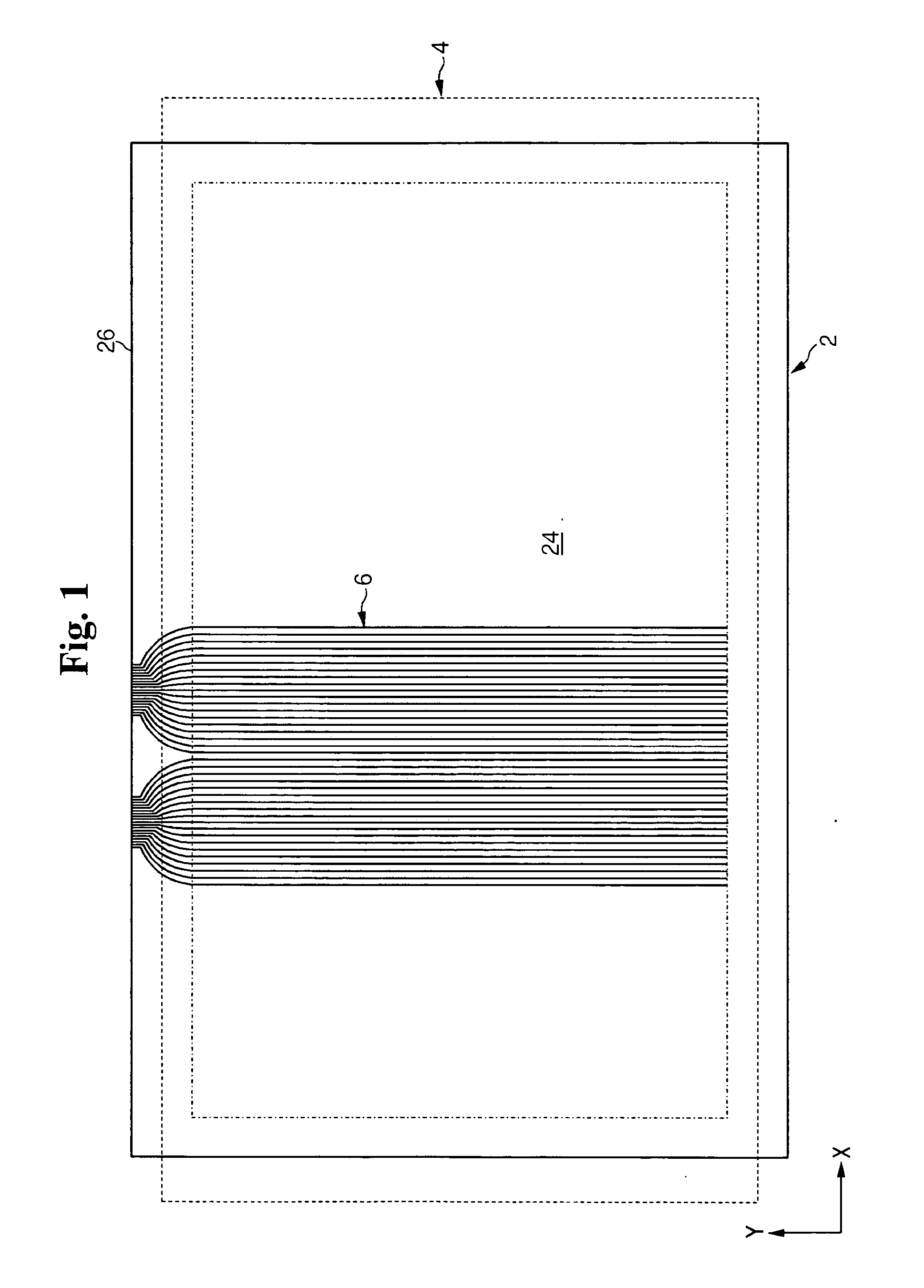
[0036] In more detail, address electrodes 6 are formed on a surface of first substrate 2 opposing second substrate 4. Address electrodes 6 are formed along one direction (e.g., direction Y). In one embodiment, address electrodes 6 are formed in a striped pattern with predetermined spacing between adjacent address electrodes 6. First dielectric layer 8 is formed over an entire inner surface of first substrate 2 covering address electrodes 6.

[0037] Barrier ribs 10 are formed on first dielectric layer 8. In one embodiment, b...


PUM


Abstract

A plasma display panel includes first and second substrates provided opposing one another with a predetermined gap therebetween. Address electrodes are formed on the first substrate. Barrier ribs defining discharge cells are mounted in a display region between the substrates. Further, discharge sustain electrodes are formed on the second substrate substantially perpendicular to the address electrodes. The electrodes are formed into groups of a predetermined number, and the electrodes include effective segments positioned in the display region, terminal segments positioned in a terminal region outside the display region and having a smaller pitch than that of the effective segments, and intermediate segments interconnecting these segments. In at least one group, lengths of elements of the terminal segments increasingly decrease as a distance from a center of the group is increased.

Description

CROSS-REFERENCE TO RELATED APPLICATIONS [0001] This application claims priority to and the benefit of Korean Patent Application No. 10-2003-0072362 filed on Oct. 16, 2003 in the Korean Intellectual Property Office, the entire content of which is incorporated herein by reference. BACKGROUND OF THE INVENTION [0002] (a) Field of the Invention [0003] The present invention relates to a plasma display panel (PDP), and more particularly, to a terminal area structure of electrodes in a PDP. [0004] (b) Description of the Related Art [0005] A PDP is a display device that uses vacuum ultraviolet rays generated by gas discharge in discharge cells to excite phosphors, thereby realizing the display of images. With its ability to realize high-resolution images, the PDP is emerging as one of the most popular flat panel display configurations used for wall-mounted televisions and other similar large-screen applications. The different types of PDPs include the AC-PDP, DC-PDP, and hybrid PDP. The AC-P...

Claims


Application Information

Patent Timeline
Patent Type & Authority Applications(United States)
IPC IPC(8): H01J11/12H01J11/22H01J11/24H01J11/26H01J11/34H01J11/36H01J11/38H01J11/40H01J11/46H01J11/48H01R12/57
CPCH01J11/46H01J11/12
Inventor KWON, JAE-IKSONG, SUNG-HO
Owner SAMSUNG SDI CO LTD
Why Eureka
Try Eureka