
Drive train for hybrid electric vehicle

a hybrid electric vehicle and drive train technology, applied in the direction of dynamo-electric converter control, multiple dynamo-motor starters, gearing, etc., can solve the problems of heat loss and fuel efficiency degradation, and achieve the effect of reducing heat loss and reducing fuel efficiency

Inactive Publication Date: 2005-04-21
NISSAN MOTOR CO LTD
View PDF3 Cites 57 Cited by
  • Summary
  • Abstract
  • Description
  • Claims
  • Application Information

AI Technical Summary

Benefits of technology

[0007] According to a first aspect of the present invention there is provided a drive train for a hybrid electric vehicle comprising: an engine that provides propulsion power by burning fuel; a first motor/generator that is selectively switched so as to act as either an electric motor to provide driving force or an electric generator to produce electric power; a second motor/generator that is selectively switched so as to act as either an electric motor to provide driving force or an electric generator to produce electric power; a third motor that provides driving force; a transmission equipped with planetary gear sets having rotatable elements that are in connecting relationships with an output shaft, the engine, and the first and second motor/generators; and a controller that controls the first and second motor/generators and the third motor so that surplus power caused by power balance between the first and second motor/generators is supplied to the third motor when the surplus power is generated.
[0008] According to a second aspect of the present invention there is provided a transmission for a hybrid electronic vehicle comprising: planetary gear sets with rotatable elements that are in connecting relationships with an output shaft, an engine, first and second motor/generators to be shifted among a plurality of running modes including a large driving force running mode, the planetary gear sets having velocity axes corresponding to the first motor/generator, the engine, an output shaft, th

Problems solved by technology

The above known conventional drive train, however, encounters a problem that when a battery is full-charged, surplus power generated by the first motor / generator is wasted into heat energy, resulting in degradation of fuel efficiency.
Furthermore, this heat loss requires measures for cooling the first motor / generator.

Method used


Image

  • Drive train for hybrid electric vehicle
  • Drive train for hybrid electric vehicle
  • Drive train for hybrid electric vehicle

Examples


Embodiment Construction

[0031] Throughout the following detailed description, similar reference characters and numbers refer to similar elements in all figures of the drawings, and their descriptions are omitted for eliminating duplication.

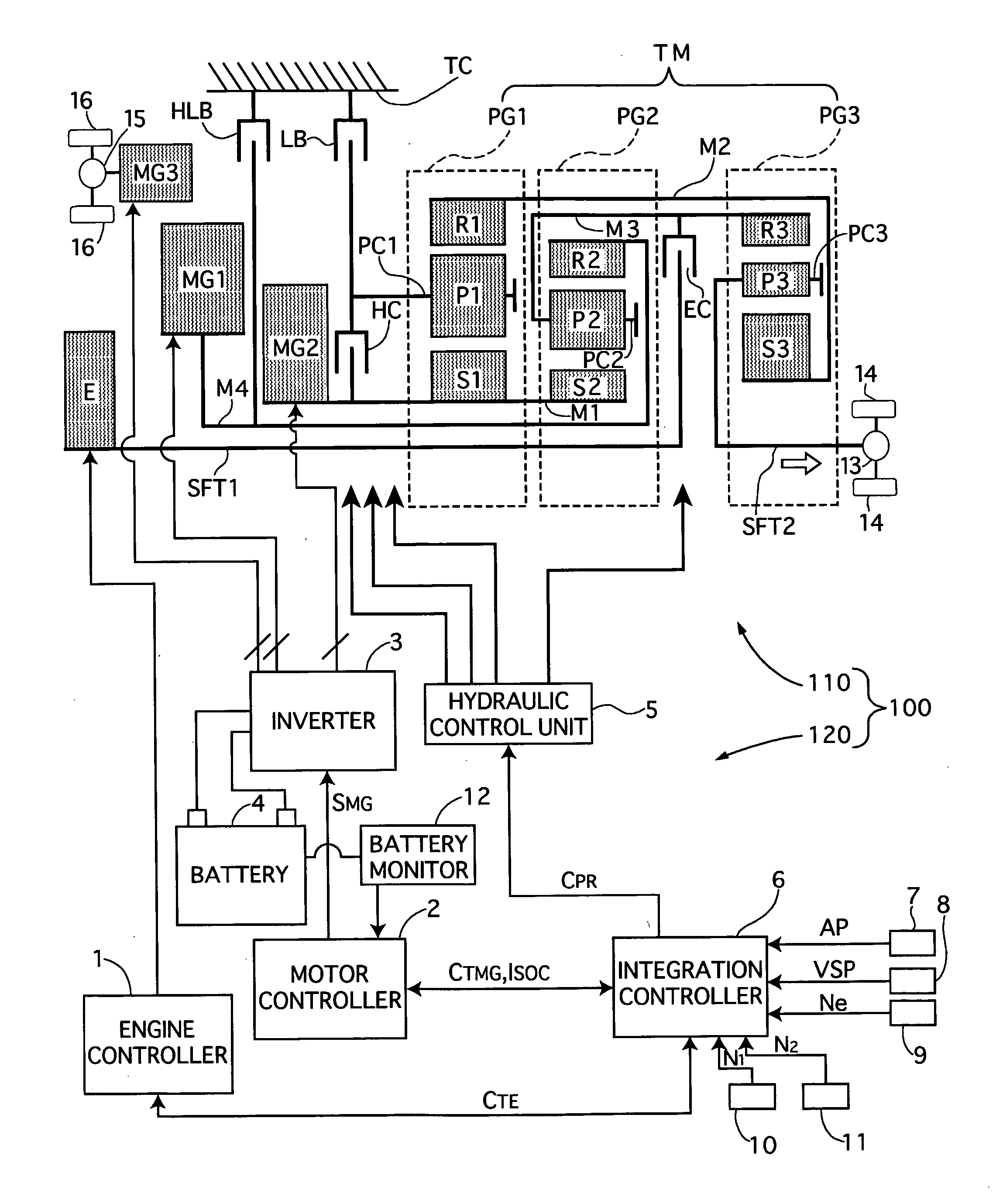
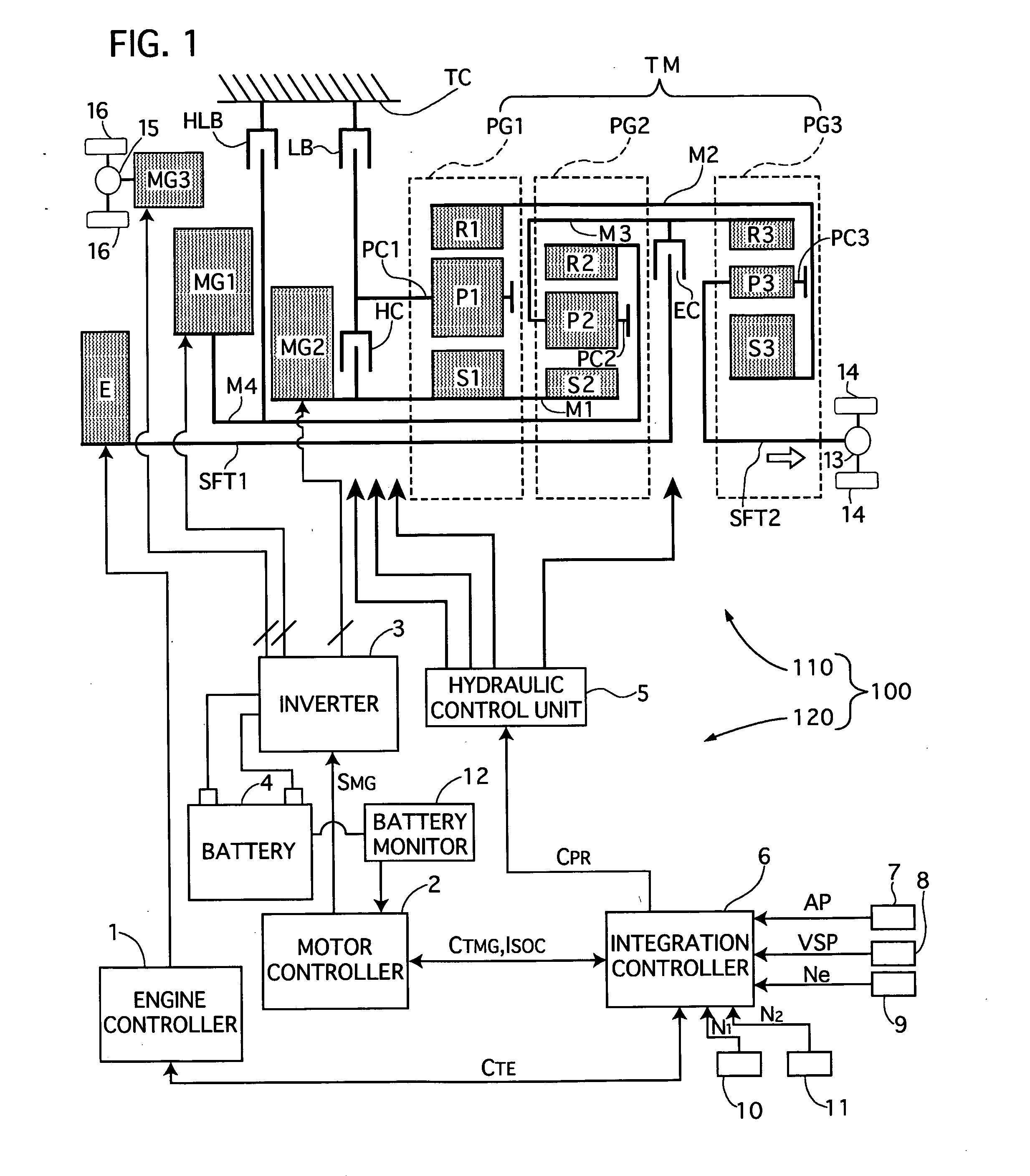
[0032] Referring to FIG. 1 of the drawing, there is shown a first preferred embodiment of a drive train for a hybrid electric vehicle according to the present invention.

[0033] The drive train 100 has a mechanical and electric drive part 110 that selectively provides mechanical and electric power or electrical power so as to apply driving force to wheels of a motor vehicle, and a hydraulic and electronic control part 120 that hydraulically and electronically controls the mechanical and electric part 110 according to driving conditions.

[0034] The mechanical and electric part 110 includes an engine E that provides propulsion power by burning fuel, a first and second electric motor / generators MG1 and MG2 that each selectively act as a motor so as to provide driving power ...


PUM


Abstract

A drive train for a hybrid electric vehicle has an engine, first and second motor / generators, a third motor, and a transmission in connecting relationships with the engine, the motor / generators, and the third motor. The transmission has planetary gear sets to be shifted among a plurality of running modes including a large driving force running mode. A controller controls surplus power caused by power balance between the first and second motor / generators to be supplied to the third motor when the surplus power is generated and the vehicle starts with the transmission being operated in the large driving force running mode.

Description

BACKGROUND OF THE INVENTION [0001] 1. Field of the Invention [0002] The present invention relates to a drive train for a hybrid electric vehicle which combines a fuel combustion engine and a electric motor / generator as power sources to propel a motor vehicle in highly efficient driving performance. [0003] 2. Description of the Related Art [0004] A drive train for a hybrid electric vehicle of this kind is disclosed in Japanese patent laying-open publication No. 2003-32808. This drive train has an engine, a first motor / generator, a second motor / generator, a differential device consisting of planetary gear sets connected with the engine, the first and second motor / generators, and a final drive. When vehicle starting, the drive train is shifted to a large driving force running mode, because large driving force is necessary for starting a motor vehicle. This running mode is set so that an amount of electricity generated by the first motor / generator at a low vehicle speed, for example 0 K...

Claims


Application Information

Patent Timeline
IPC IPC(8): B60K1/02B60K6/365B60K6/44B60K6/52B60W10/08B60W10/10B60W10/26B60W20/00F16H3/72
CPCB60K1/02Y02T10/6265B60K6/44B60K6/52B60W10/08B60W10/10B60W10/26B60W20/00B60W2510/244F16H3/728F16H2037/102F16H2037/104F16H2037/106F16H2200/201Y02T10/623B60K6/365Y02T10/62B60W20/10
Inventor AIZAWA, TAKEOONOYAMA, TAIICHI
Owner NISSAN MOTOR CO LTD
Learn More