Vehicle transmission having continuously variable gear ratios

a transmission ratio and continuously variable technology, applied in the direction of gear elements, belts/chains/gearrings, mechanical instruments, etc., can solve the problems of complicated shifting process, feature disadvantages of relatively complex design, etc., and achieve low “drive range, high transmission ratio, and transmission ratio reduction

Inactive Publication Date: 2011-06-30
SCHAEFFLER TECH AG & CO KG
View PDF19 Cites 1 Cited by
  • Summary
  • Abstract
  • Description
  • Claims
  • Application Information

AI Technical Summary

Benefits of technology

[0008]That means, in other words, that according to the present invention at least one of the torque transmission devices no longer exists in the form of a clutch, but rather in the form of a freewheel. That also eliminates the necessity to have to control the omitted clutch. The arrangement of freewheel / freewheels is provided in that it blocks or engages in the desired torque transmission direction, and it can be overrun in the opposite direction without the blocking effect.
[0009]According to a preferred embodiment, the input shaft and the intermediate shaft are coaxial, and the torque transmission devices are controlled such that a “Low” driving range with a high transmission ratio and a lower transmission ratio “High” driving range arise, so that the vehicle transmission according to the invention has a large total transmission ratio.

Problems solved by technology

Although the above-described transmission has already proven itself, it features the disadvantage of entailing a relatively complex design because it features five clutches altogether, of which one clutch is assigned to the reverse driving range although four clutches are necessary for the conical disk belt transmission that is repeated twice for a large total ratio.
Those clutches must be activated accordingly, which leads to complicated shifting processes.

Method used


Image

  • Vehicle transmission having continuously variable gear ratios
  • Vehicle transmission having continuously variable gear ratios
  • Vehicle transmission having continuously variable gear ratios

Examples


first embodiment

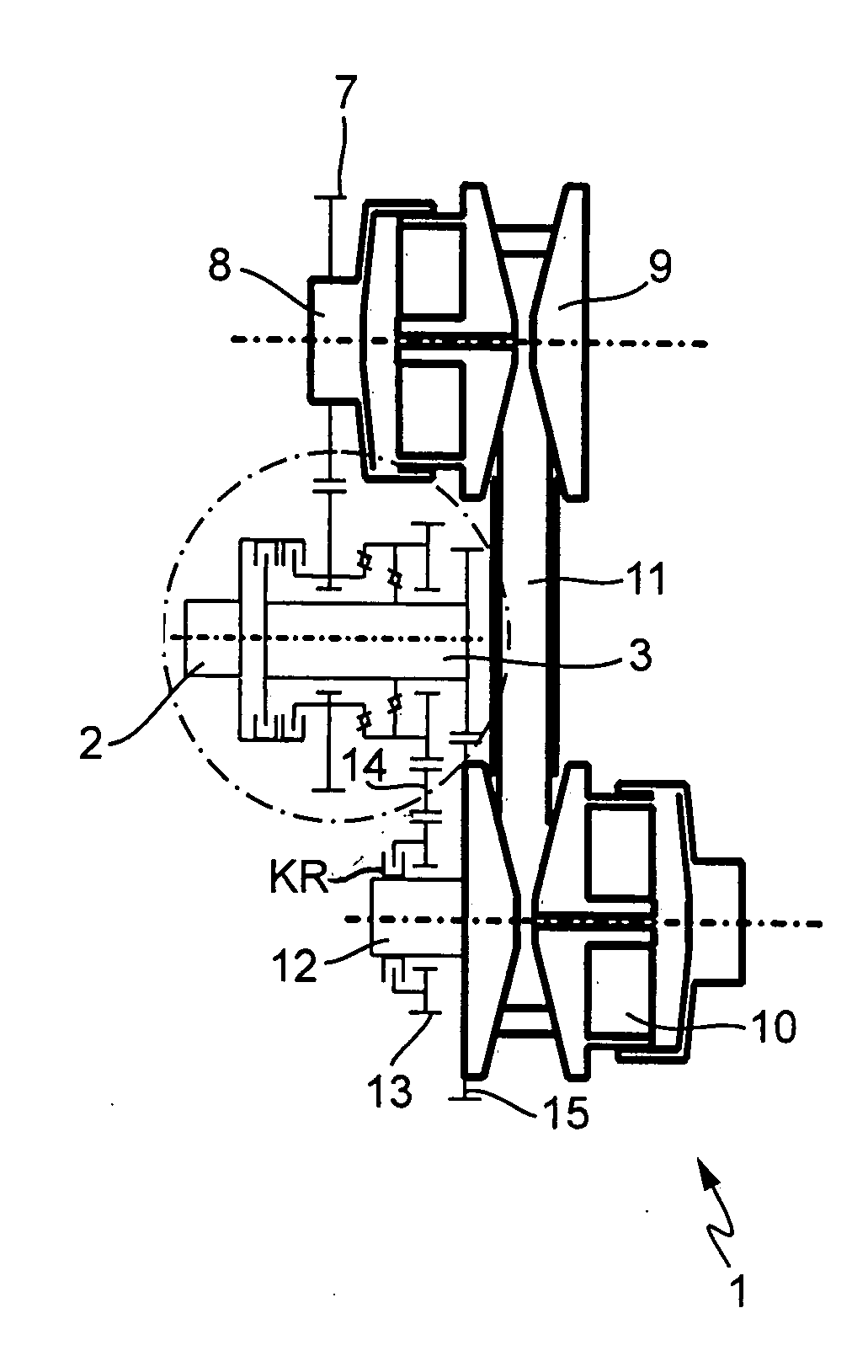
[0027]FIG. 1 of the drawings shows a principle representation of a vehicle transmission 1 in accordance with a first embodiment according to the present invention.

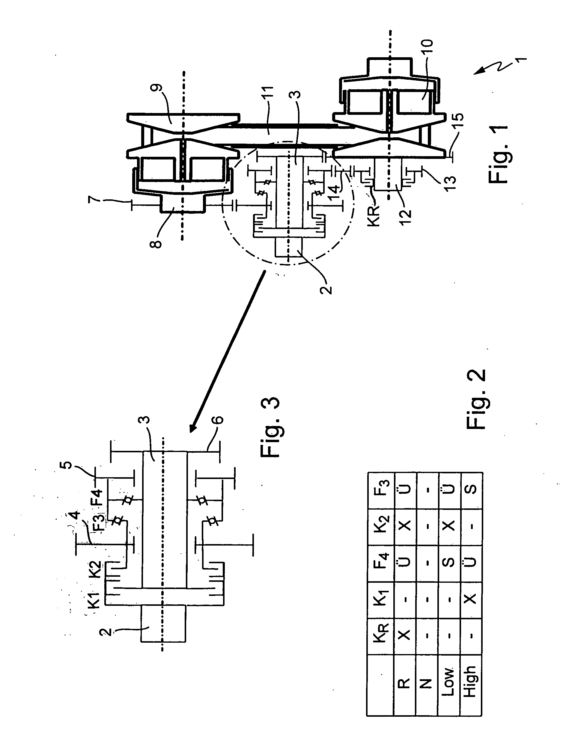
[0028]The vehicle transmission 1 features an input shaft 2, through which drive torque from an internal combustion engine (not represented) can be introduced into the vehicle transmission 1. On an intermediate shaft 3, an intermediate gear 4 and an output gear 5 are supported rotatably, which is visible in the detail shown in FIG. 3 that is based on the represented structure of the design of the encircled section according to FIG. 1. A connecting gear-6 is disposed non-rotatably on the intermediate shaft 3 and serves for the introduction of torque into the intermediate shaft 3. As more closely evident from FIG. 3, a clutch K1 is disposed on the input shaft 2 in order to enable torque transmission from the input shaft 2 into the intermediate shaft 3 when the clutch K1 is engaged. Though a second clutch K2, torque can be tra...

second embodiment

[0037]FIG. 5 of the drawings shows a vehicle transmission in FIG. 6 the design and the arrangement of two clutches and two freewheels, and in FIG. 7 the representation of a matrix of the positions of the clutches and freewheels in different driving ranges of the vehicle transmission according to FIG. 5. As it is evident in this embodiment, freewheel F1 is disposed between the input shaft 2 and the intermediate shaft 3, and a further freewheel F4 between the intermediate shaft 3 and the output gear 5. A clutch K2 is disposed in the torque transmission path between the input shaft 2 and the intermediate gear 4.

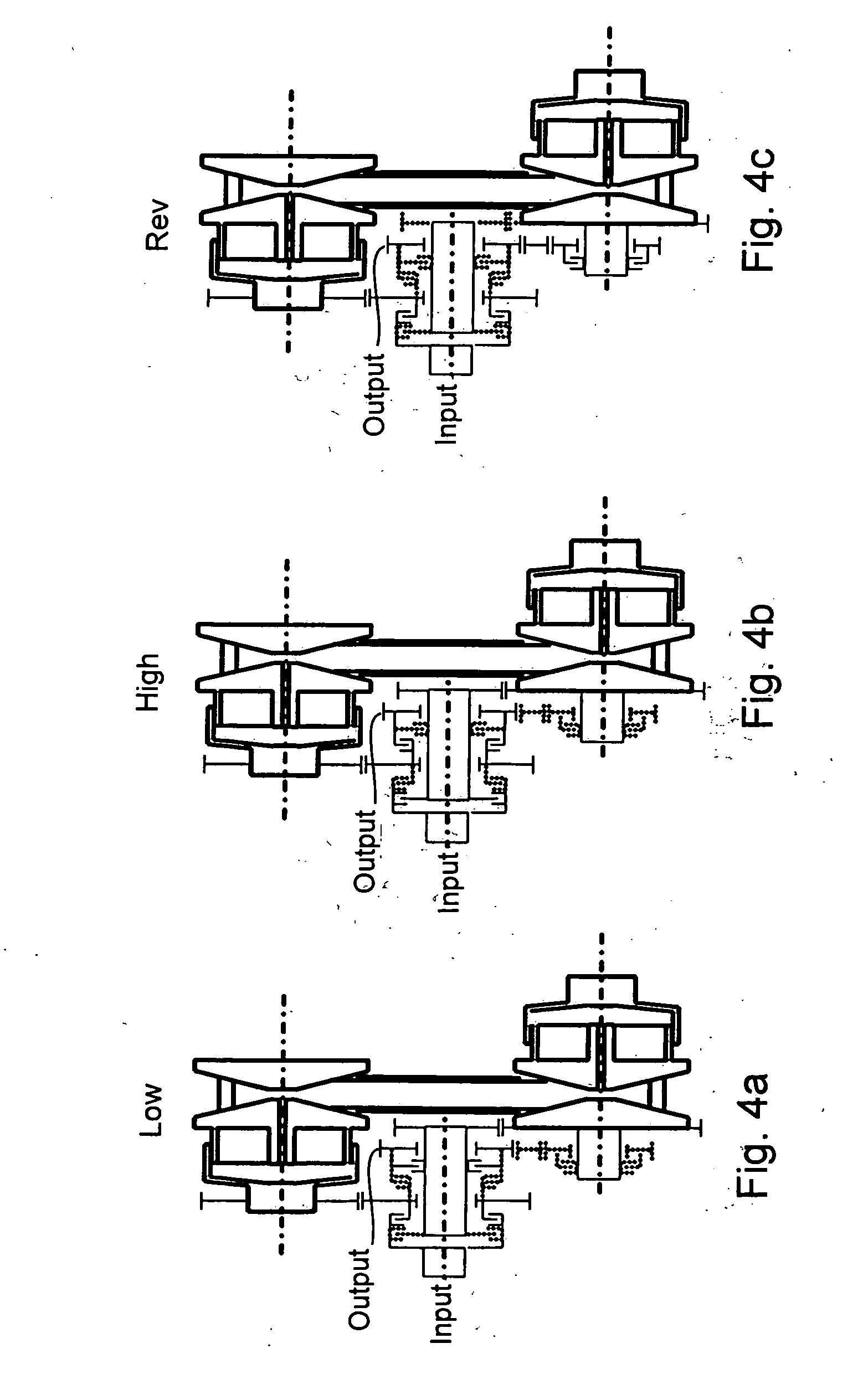
[0038]In the matrix shown in FIG. 7, in the driving range “Rev,” the reverse drive clutch “KR” is engaged, freewheel F1 is overrun just as freewheel F4 is overrun, and the clutch K2 is engaged. The torque path, or rather the torque transmission path, corresponds at the same time to the representation “Rev” in accordance with FIG. 4c of the drawings.

[0039]In the driving range “L...

third embodiment

[0041]FIG. 8 of the drawings shows a principle representation of a vehicle transmission according to the present invention in a In FIG. 9, the design and arrangement of two clutches and two freewheels is shown, and in FIG. 10 the representation of a matrix of the positions of the clutches and freewheels is shown in different driving ranges of the vehicle transmission according to FIG. 8.

[0042]In the transmission according to the third embodiment, freewheel F1 is disposed between the input shaft 2 and the intermediate shaft 3. Likewise, a freewheel F2 is disposed between the input shaft 2 and the intermediate gear 4. A clutch K3 is disposed in the torque transmission path between the intermediate gear 4 and the output gear 5, and a further clutch K4 is disposed between the intermediate shaft 3 and the output gear 5.

[0043]The formation of the part of the transmissions according to FIG. 5 and FIG. 8 required for the reverse movement of the vehicle corresponds with the arrangement of t...


PUM


Abstract

A vehicle transmission having continuously variable transmission ratios including an input shaft and an intermediate shaft. A first conical disk pair is disposed on a first shaft and a second conical disk pair is disposed on a second shaft. A belt connects the disk pairs. An intermediate gear that can be rotatably engaged with the first shaft, and an output gear, are rotatably supported on the intermediate shaft. A connecting gear is non-rotatably disposed on the intermediate shaft. A first force transmitting device is disposed between the input shaft and intermediate shaft, a second force transmitting device is disposed between the input shaft and the intermediate gear, a third force transmitting device is disposed between the intermediate gear and output gear, and a fourth force transmitting device is disposed between the intermediate shaft and the output gear. At least one of the force transmitting devices is a freewheel.

Description

BACKGROUND OF THE INVENTION[0001]The present invention relates to a vehicle transmission having continuously variable transmission ratios, with a first conical disk pair disposed on a first shaft and a second conical disk pair disposed on a second shaft. A a belt means is disposed between the conical disk pairs, as well as an input shaft and an intermediate shaft. On the intermediate shaft an intermediate gear that can be brought in into rotational engagement with the input shaft and an output gear are rotatably supported and a connecting gear is disposed non-rotatably. Between the input shaft and the intermediate shaft a first torque transmission device is disposed, and between the input shaft and the intermediate gear a second torque transmission device is disposed. Between the intermediate gear and the output gear a third torque transmission device is disposed, and between the intermediate shaft and the output gear a fourth torque transmission device is disposed.[0002]Based on th...

Claims


Application Information

Patent Timeline
Patent Type & Authority Applications(United States)
IPC IPC(8): F16H37/02F16H31/00
CPCF16H37/021F16H2037/025F16H2037/023
Inventor TRILLER, ANDREAS
Owner SCHAEFFLER TECH AG & CO KG
Why Eureka
Try Eureka