Magnetic pattern forming method, magnetic pattern forming apparatus, magnetic disk, and magnetic recording apparatus

a magnetic pattern and forming method technology, applied in the direction of maintaining head carrier alignment, nanoinformatics, instruments, etc., can solve the problems of time-consuming one-by-one formation of irregularities, high cost, and difficulty in executing track position control with high accuracy and recording servo signals with high precision. , to achieve the effect of efficient forming a minute magnetic pattern, high precision and high density

Inactive Publication Date: 2005-04-21
SEO YUZO +3
View PDF7 Cites 6 Cited by
  • Summary
  • Abstract
  • Description
  • Claims
  • Application Information

AI Technical Summary

Benefits of technology

[0029] The present invention has been developed with a view to eliminating the above-mentioned problems, and it is therefore an object of the invention to provide a magnetic pattern forming method and apparatus pertaining to a technique of forming a magnetic pattern on a magnetic recording medium by means of a combination of local heating and exposure to an external magnetic field, and capable of efficiently forming a minute magnetic pattern with higher precision, and in its turn offer a higher-density magnetic disk and magnetic recording apparatus in a small amount of time and at a low cost.

Problems solved by technology

However, since the center of gravity of the positioning mechanism and the center of gravity of the actuator exist at different positions, difficulty is encountered in executing track position control with high accuracy and recording a servo signal with a high precision.
There are problems which arises with this technique, however, in that an unstable state of a flying head due to the irregularities exerts adverse influence on recording / reproduction, cost rises because there is a need to use a high-power laser beam for the formation of the irregularities, and the one-by-one formation of the irregularities is time-consuming.
Thus, although the above-mentioned technique is relatively applicable to a flexible floppy disk easy to press or a low-corecivity magnetic disk which does not require too great contact, considerable difficulty is experienced in applying it to a high-density recording magnetic disk using a hard substrate, whose corecivity exceeds 3000 Oe.
That is, in the case of the magnetic disk using a hard substrate, there is a possibility that microscopic dirt particles or the like get between the master disk and the medium at the contact to produce defects on the medium or damage the high-priced master disk.
In particular, for a glass substrate, the contact therebetween does not reach satisfaction because the dirt particles get therebetween, which makes the magnetic print impossible or causes cracks on the magnetic recording medium.
Furthermore, with the technique disclosed in U.S. Pat. No. 3,869,711, although a pattern formed obliquely with respect to a track direction of a disk is recordable, the recording is limited to the formation of only a pattern with a low signal strength.
However, in the case of the oblique pattern, a magnetic field for the reverse magnetization becomes perpendicular to a gap defined by the ferromagnetic layer of the master disk, which makes it difficult to tilt the magnetization in a desired direction.
In consequence, a part of the magnetic field escapes to the ferromagnetic layer to make it difficult to expose a desired portion to a sufficient magnetic field at magnetic print so that a sufficient reverse magnetization pattern is difficult to form and a high signal strength is hard to obtain.
Moreover, since the area subjected to recording is limited to the heating area while the recording in other than the heating area cannot be made even if a magnetic field is brought to strike thereon, the recording of a clear magnetic pattern is possible without bringing a mask or the like into contact with the medium.
If the magnetic pattern is made more minute up to 1 to 2 μm or formed in terms of submicron, because of the limit to the processing accuracy, difficulty can be encountered in patterning a mask with high precision, and the alignment precision between the mask and the medium can deteriorate so that a magnetic pattern cannot be formed with sufficiently high accuracy.

Method used


Image

  • Magnetic pattern forming method, magnetic pattern forming apparatus, magnetic disk, and magnetic recording apparatus
  • Magnetic pattern forming method, magnetic pattern forming apparatus, magnetic disk, and magnetic recording apparatus
  • Magnetic pattern forming method, magnetic pattern forming apparatus, magnetic disk, and magnetic recording apparatus

Examples


first embodiment

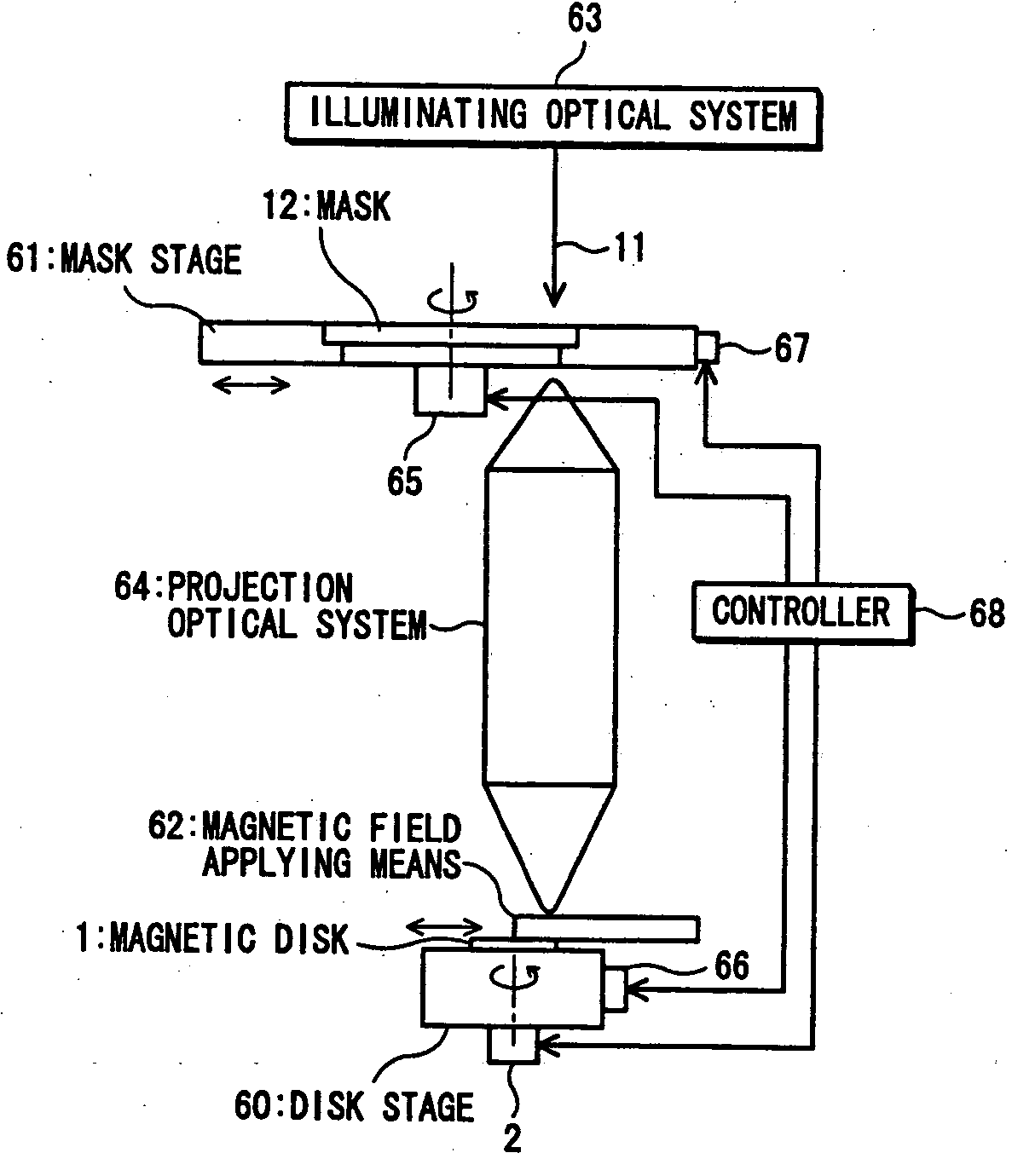
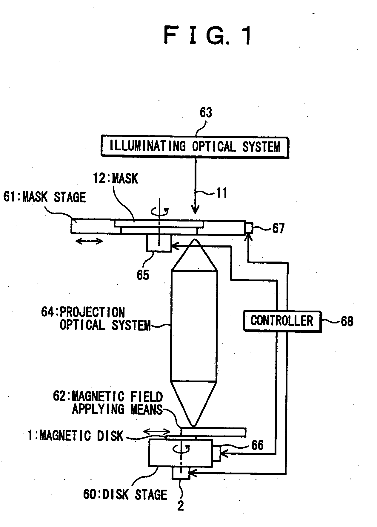
[0087] Referring to FIGS. 1 to 5, a description will be given hereinbelow of a magnetic pattern forming apparatus and method according to a first embodiment of the present invention.

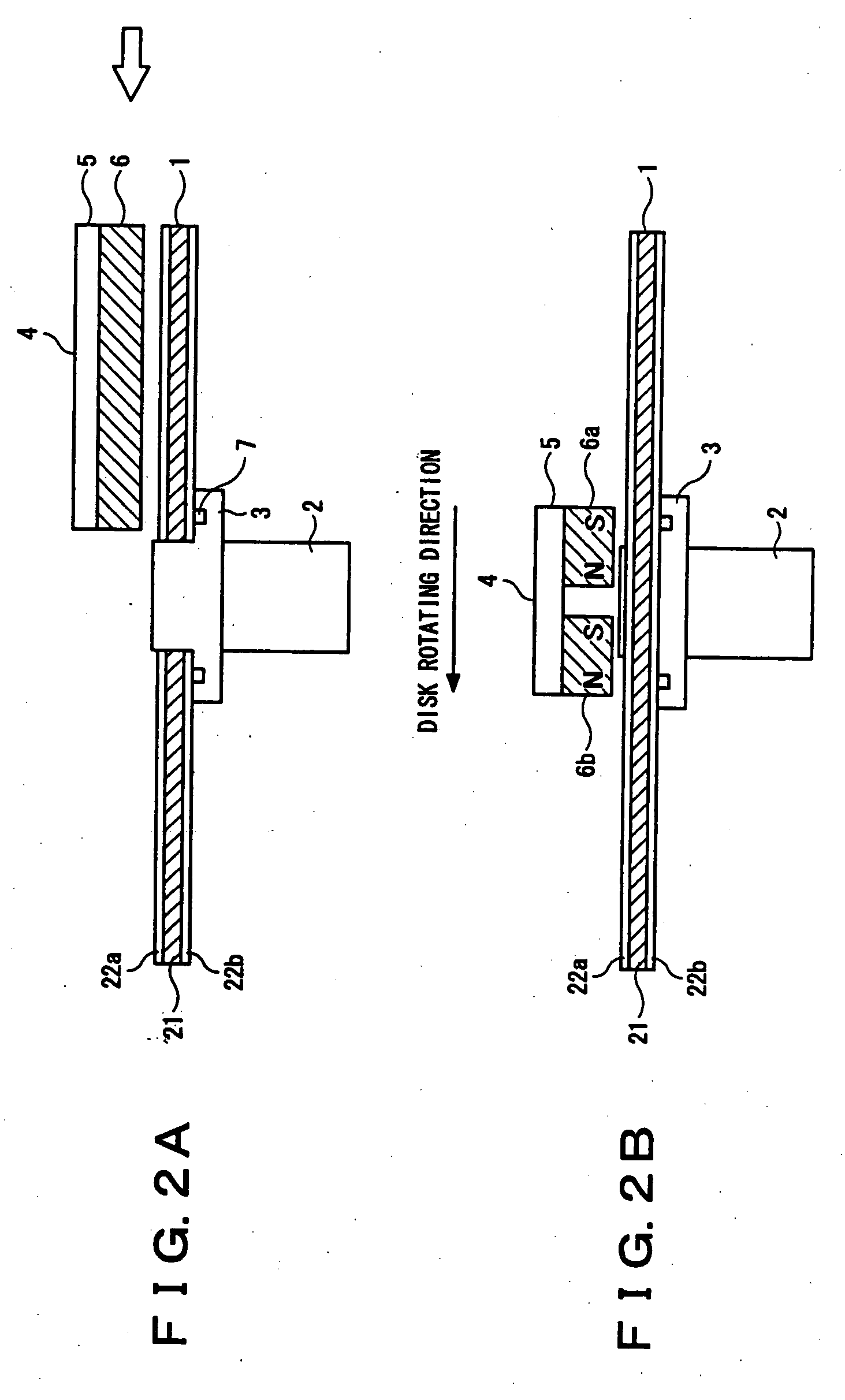
[0088] Secondly, a description will be given of a magnetic disk on which a magnetic pattern is formed through the use of a magnetic pattern apparatus (method) according to this embodiment.

[0089] According to this embodiment, a magnetic disk is made as follows. That is, usually, a hard substrate is used as a substrate for a magnetic disk, for that there is a need to prevent it from vibrating even when a high-speed rotation takes place at fast recording / reproduction. To provide a sufficient rigidity against the vibration, in general, it is preferable that the thickness of the substrate is equal to or more than 0.3 mm. However, since a high thickness adversely affects the thickness reduction of a magnetic recording apparatus, preferably, it is less than or equal to 3 mm. For example, among the substrates,...

second embodiment

Description of Second Embodiment

[0325] Furthermore, referring to FIGS. 7, 8, 9A and 9B, a description will be given hereinbelow of a magnetic pattern forming apparatus and method, magnetic disk and magnetic recording apparatus according to a second embodiment of the present invention.

[0326] A difference of the magnetic pattern forming apparatus according to this embodiment from the above-described first embodiment is a construction for scanning with an energy beam in radial directions of a magnetic disk and a mask.

[0327] That is, in the above-described first embodiment, the illuminating optical system 63, the projection optical system. 64 and the magnetic field applying means 62 are set in fixed conditions and the disk stage 60 and the mask stage 61 are moved (operated for scanning) in a direction orthogonal to the energy beam 11 (the optical axis of a laser beam) given through the illuminating optical system 63 and the projection optical system 64, whereas in this embodiment, as ...

third embodiment

Description of Third Embodiment

[0361] Furthermore, referring to FIG. 10, a description will be given hereinbelow of a magnetic pattern forming apparatus and method, magnetic disk and magnetic recording apparatus according to a third embodiment of the present invention.

[0362] A difference of the magnetic pattern forming apparatus according to this embodiment from the apparatus according to the above-described first embodiment is a construction for making a scan with an energy beam in radial directions of a magnetic disk and a mask.

[0363] That is, in the above-described first embodiment, the illuminating optical system 63, the projection optical system 64 and the magnetic field applying means 62 are set in fixed conditions and the disk stage 60 and the mask stage 61 are moved (operated for scanning) in a direction orthogonal to the energy beam 11 (the optical axis of a laser beam) given through the illuminating optical system 63 and the projection optical system 64, whereas in this ...


PUM

PropertyMeasurementUnit
widthaaaaaaaaaa
thicknessaaaaaaaaaa
thicknessaaaaaaaaaa

Abstract

A magnetic pattern forming apparatus, which is designed to form a desired magnetic pattern on a magnetic disk having a magnetic layer on a substrate, is made up of a mask having a pattern identical or similar to the desired magnetic pattern, a projection optical system for exposing the magnetic disk to a spot-like energy beam coming through the mask to heat the magnetic layer for projecting the mask pattern to the magnetic disk at a one-to-one ratio or a predetermined reduction ratio, a magnetic field applying device for applying an external magnetic field to the magnetic disk, a control unit for conducting scanning with the spot-like energy beam with respect to the magnetic disk and the mask in their radial directions while rotating the magnetic disk and the mask.

Description

BACKGROUND OF THE INVENTION [0001] (1) Field of the Invention [0002] The present invention relates to a magnetic pattern forming method and apparatus for use in a magnetic recording apparatus (magnetic disk), and more particularly to a magnetic pattern forming method and apparatus, magnetic disk and magnetic recording apparatus suitable for recording / reproduction (readout) by a flying / contact head. [0003] (2) Description of the Related Art [0004] Magnetic recording apparatus represented by a magnetic disk unit (hard disk drive) have come into widespread use as an external storage of information processing equipment such as computers, and in the recent years, they are being used as a moving-picture recording apparatus or a recording apparatus for a set-top box. [0005] The magnetic disk unit (hard disk drive) is usually made up of a shaft for fixing one magnetic disk or a plurality of magnetic disks in a skewering manner, a motor for turning the magnetic disk joined through a bearing ...

Claims


Application Information

Patent Timeline
Patent Type & Authority Applications(United States)
IPC IPC(8): G11B11/10G11B5/00G11B5/012G11B5/02G11B5/55G11B5/596G11B5/82G11B5/84G11B5/855G11B13/04
CPCB82Y10/00G11B5/012G11B5/553G11B5/59633G11B2005/0029G11B5/82G11B5/855G11B13/045G11B2005/0021G11B5/743
Inventor SEO, YUZOIKEDA, HIROYUKIKURIWADA, TAKESHIKURIYAMA, TOSHIHIKO
Owner SEO YUZO
Why Eureka
Try Eureka