Programmable light source for edge-lit displays

a technology of edge illumination and light source, which is applied in the direction of lighting and heating equipment, instruments, mechanical equipment, etc., can solve the problems of nontrivial task of manufacturing a safe, reliable, energy-efficient, long-lasting, and efficient light transmission

Inactive Publication Date: 2005-04-21
BOKS HERBERT JAN KARL
View PDF5 Cites 17 Cited by
  • Summary
  • Abstract
  • Description
  • Claims
  • Application Information

AI Technical Summary

Benefits of technology

[0006] The basic function of an edge-illumination device is to efficiently transmit light into an edge of a transparent display panel. Ideally, the light is evenly distributed over the edge of the transparent display panel and transmitted in a direction nearly parallel to the display surface of the display panel.

Problems solved by technology

The technological advancements made through the prior art notwithstanding, problems exist with current products.
First, achieving a directed, uniform light distribution is a challenging task.
Third, manufacturing an energy-efficient, long-lasting, safe, and reliable product has been shown to be a nontrivial task.

Method used


Image

  • Programmable light source for edge-lit displays
  • Programmable light source for edge-lit displays
  • Programmable light source for edge-lit displays

Examples


Embodiment Construction

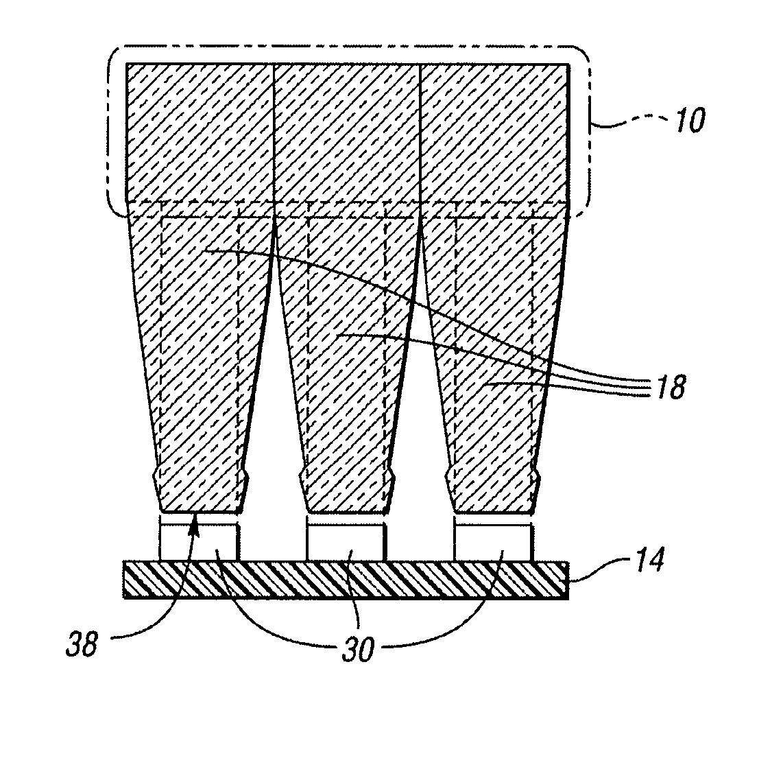
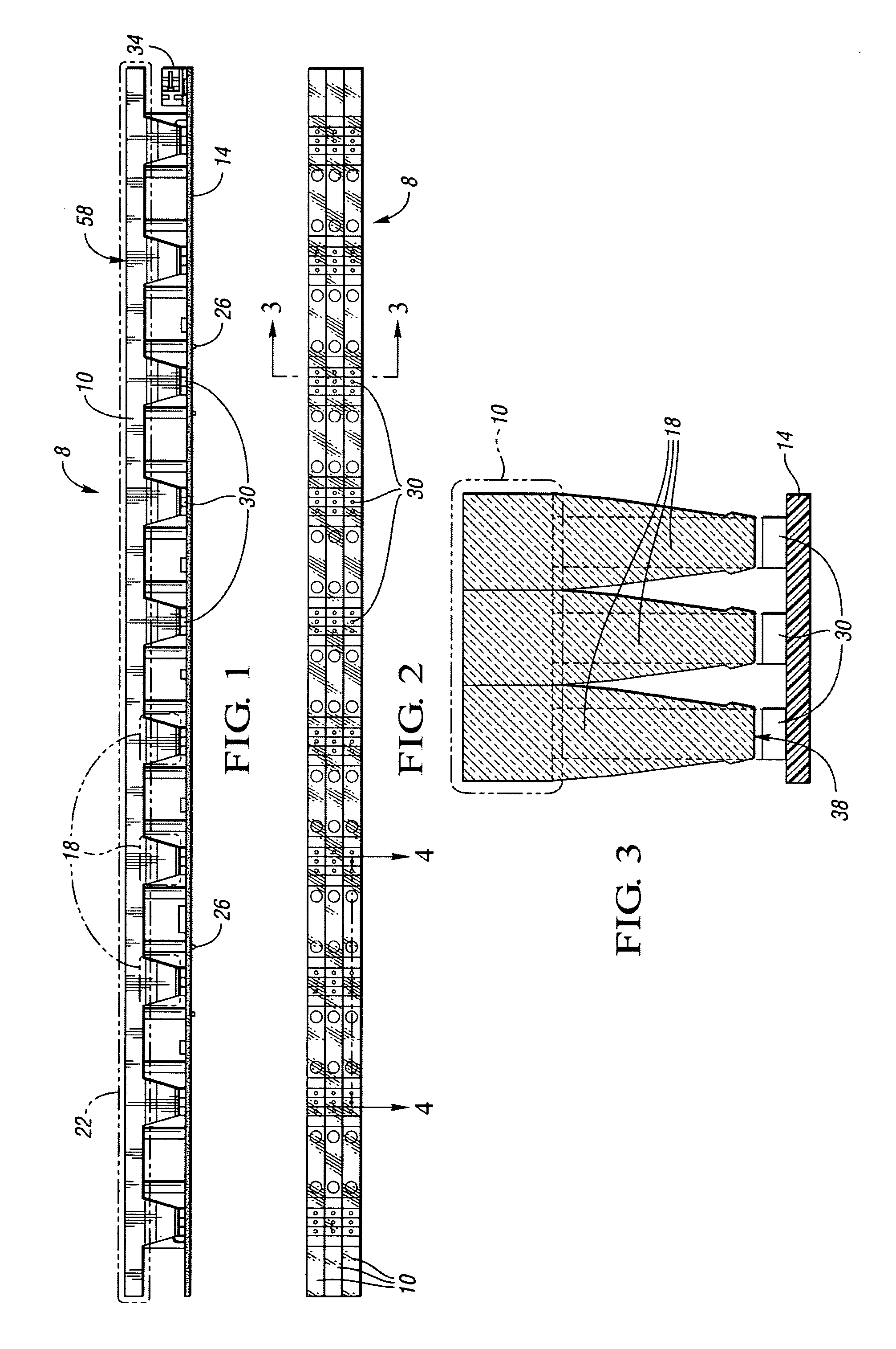
[0019] Referring to FIGS. 1 and 2, an illumination device 8, which includes a transparent body 10 and printed circuit board 14, is schematically depicted. The transparent body 10 includes a plurality of collimating lenses 18, a connecting portion 22 which connects the lenses 18 in a serial arrangement, and a plurality of hook-shaped mounting brackets 26 which provide a rigid connection of the transparent body 10 to the printed circuit board 14. The printed circuit board 14 includes a plurality of light emitting diodes (LEDs) 30 which, once the transparent body 10 and printed circuit board 14 are rigidly attached, are each positioned adjacent a corresponding one of the plurality of collimating lenses 18. The printed circuit board 14 also includes an electronic connector 34, located near one of the longitudinal ends of the printed circuit board 14.

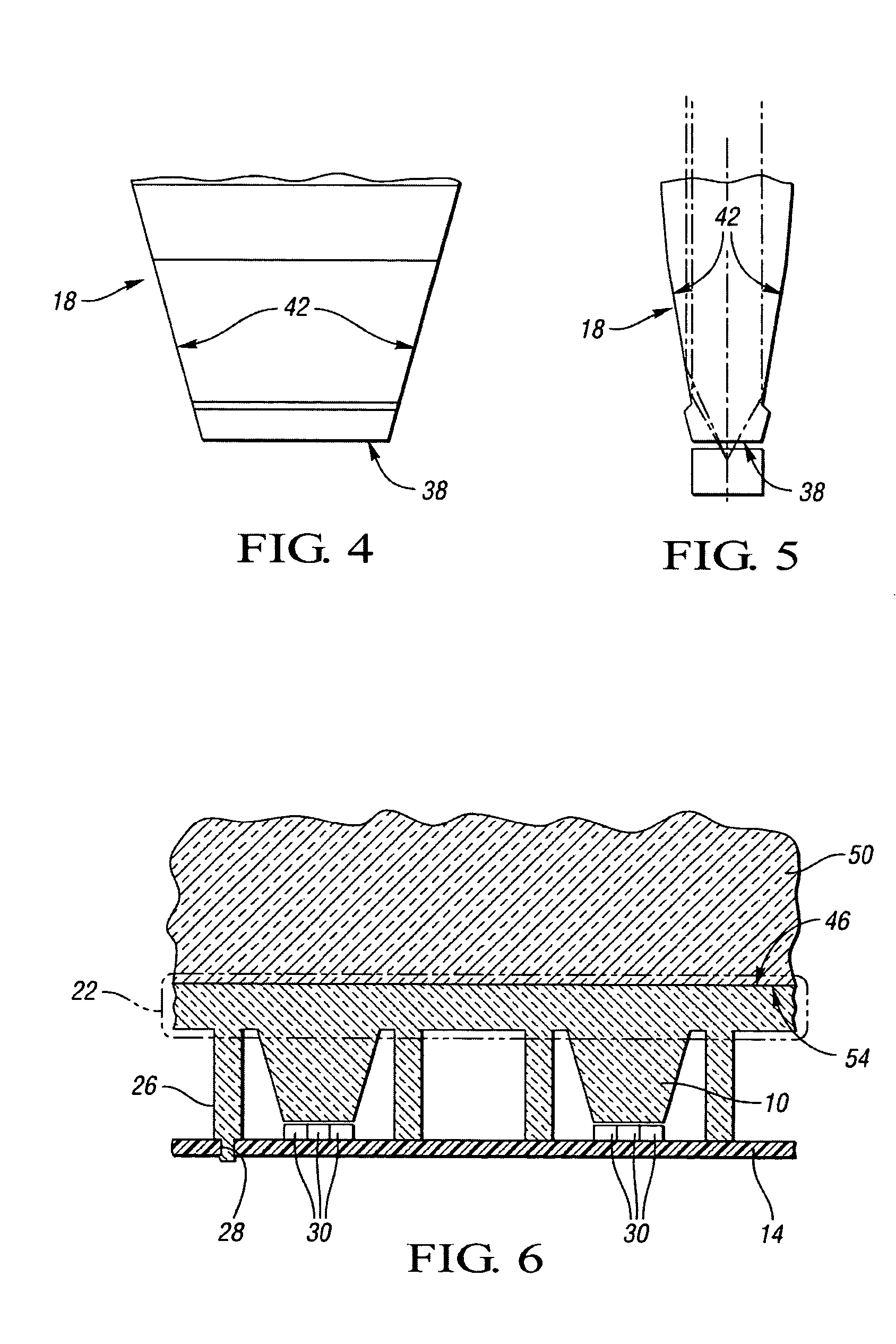
[0020] Referring to FIG. 3, wherein like reference numbers refer to like components from FIGS. 1 and 2, each of the plurality of collimati...


PUM


Abstract

A light source comprised of a transparent body and a printed circuit board is mounted to a transparent display panel. The transparent body is comprised of a series of light-collimating lenses. The printed circuit board comprises a series of LEDs which are arranged such that the emitted light enters the collimating lenses and then enters the transparent display panel. The substantially collimated light reflects within the display panel until it contacts a diffuse surface portion, causing the light to exit the display panel. The on/off state and intensity of the LEDs are controlled by a programmable device. The transparent body and transparent display panel are sufficiently flat to facilitate a layered arrangement of assemblies.

Description

CROSS-REFERENCE TO RELATED APPLICATION [0001] This application claims the benefit of U.S. Provisional Application 60 / 511,900, filed Oct. 16, 2003, which is hereby incorporated by reference in its entirety.TECHNICAL FIELD [0002] This invention relates to an illumination device for edge-illumination of a transparent display panel. BACKGROUND OF THE INVENTION [0003] An illumination device for edge-illumination of a transparent display panel typically includes a light source in the form of a fluorescent tube mounted in the vicinity of the edge of a transparent display panel. The light emitted from the light source is directed into the transparent display panel and reflects between the inner surfaces of the transparent display panel until the light strikes a diffuse region, which causes the light to scatter and exit the transparent display panel. This principle is employed primarily in backlights of LCD displays, in lighted poster signs, in lighted name plates, in lighted EXIT signs, and...

Claims


Application Information

Patent Timeline
Patent Type & Authority Applications(United States)
IPC IPC(8): A47F3/00F21V7/04F21V8/00H03H9/00
CPCG02B6/0068G02B6/0028
Inventor BOKS, HERBERT JAN KARL
Owner BOKS HERBERT JAN KARL
Why Eureka
Try Eureka