Solar polymer light bar

Inactive Publication Date: 2017-04-27
KRUMWEIDE LOREN D
View PDF5 Cites 0 Cited by
  • Summary
  • Abstract
  • Description
  • Claims
  • Application Information

AI Technical Summary

Benefits of technology

[0018]Another advantage of the Solar Polymer Light Bar is the LEDs can be wired through a transformer to house current and set up with a wall switch.
[0019]Another advantage of the Solar Polymer Light Bar is that a variety of upper light accumulators and lower light dispersers can change the lighting intensity and effects.
[0020]Another advantage of the Solar Polymer Light Bar is it can have a variety of light mounting ceiling canisters and light fixtures.
[0021]Another advantage of the Solar

Problems solved by technology

The creation of the Solar Tubes using the sun's rays as a means of lighting has been very successful but it has some limitations.
The large hole has to be cut in the roof and the large ducting down can sometimes be a problem.
Fiber optic cables deliver light effectively but are very expensive and the individual lines are very small.
This complicated system does not provide the compact, inexpensi

Method used


Image

  • Solar polymer light bar
  • Solar polymer light bar
  • Solar polymer light bar

Examples


Embodiment Construction

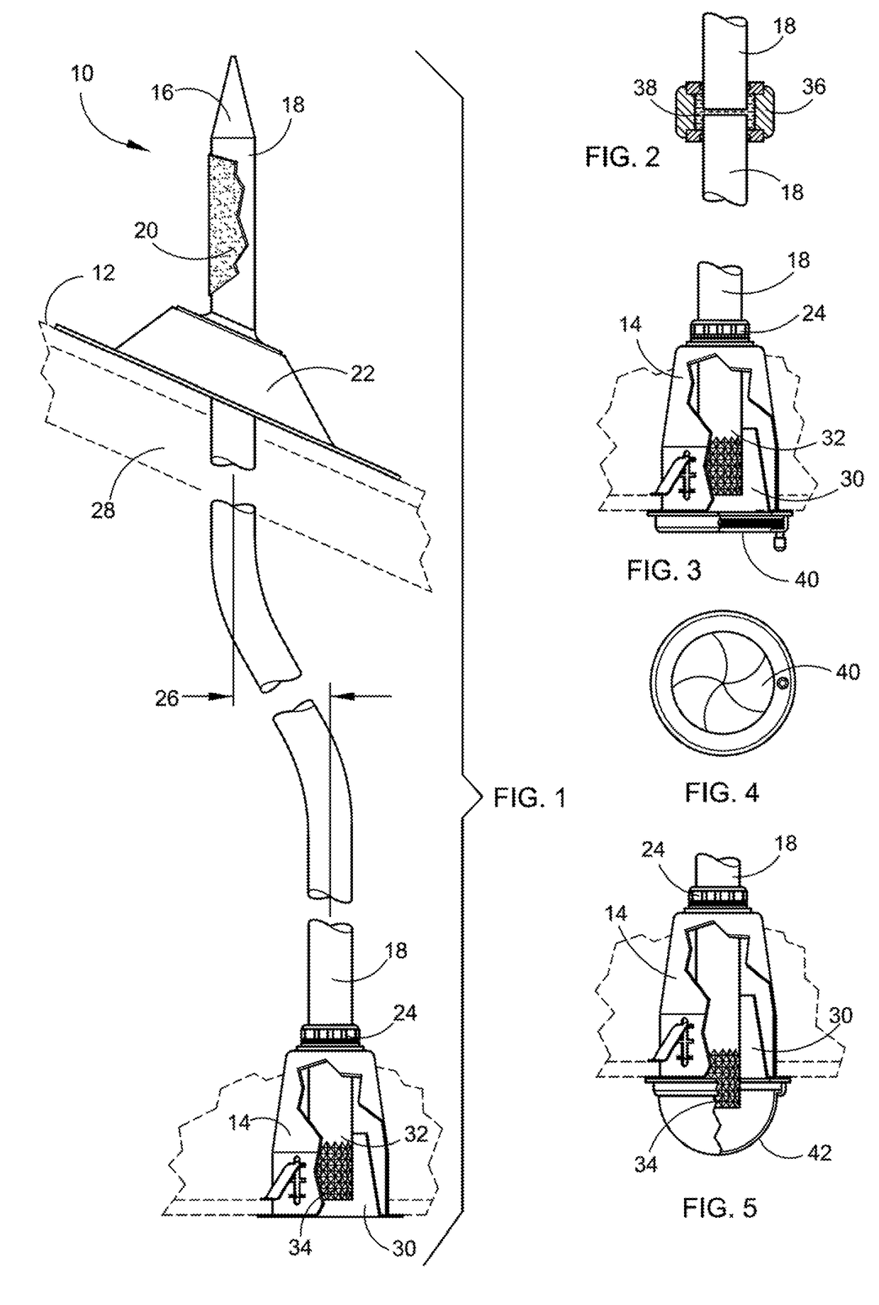
[0050]Referring now to the drawings, wherein similar parts of the Solar Polymer Light Bar 10 are identified by like reference numerals, there is seen in FIG. 1 a side view of the Solar Polymer Light Bar 10 installation through a roof 12 and down into a conventional flush ceiling light canister 14. The top conical section 16 of the polymer bar 18 can have other shapes to effectively increase the surface area for sunlight absorption. The polymer bar 18 can be left clear or have silvered reflective coating 20. The polymer bar 18 will extend through a conventional roof pipe flange 22 down to the bar clamping nut 24 of the ceiling light canister 14. The polymer bar 18 is bent in an offset configuration 26 to allow for location adjustments and articulation around construction members 28. The offset configuration 26 can be preordered to vary from two to twelve inches. A light reflective silvered insert 30 is a conventional part of light canisters 14. The lower end 32 of the polymer bar 18 ...


PUM


Abstract

The present invention is to direct sunlight through the Solar Polymer Light Bar using an exposed solid polymer bar or equivalent through a roof pipe flange down into a flush mounted ceiling light canister and a wide variety of mounting fixtures, including one or more interconnected light canisters, whereby the Solar Polymer Light Bar may be bent as required to avoid roof structural elements and ceiling structural elements when being installed. Optional light gathering and light emitting enhancement means can be added at the upper portion and lower portion of the solid polymer light bar, respectively. Solar powered, battery powered or house AC or DC transformer powered LEDs, CFLs or conventional incandescent light bulbs may be added to increase the light intensity emitted through the night time and dark hours if desired.

Description

FIELD OF THE INVENTION[0001]This application provides a means to conduct sunlight through one or more exposed polymer bars down to a variety of different lighting fixtures with the optional addition of attached LEDs, CFLs or conventional incandescent light bulbs.BACKGROUND OF THE INVENTION[0002]There exists a growing need for the saving of electrical power in homes and business structures. Solar panels have created a great awareness of the capability of using the sun's radiant energy as a power source that can be converted into electrical energy. The creation of the Solar Tubes using the sun's rays as a means of lighting has been very successful but it has some limitations. They deal with primarily ten to twelve-inch diameter fixtures that in many cases deliver too much light for accent lighting, which usually use several small lights in a row. The large hole has to be cut in the roof and the large ducting down can sometimes be a problem. Additionally, hallways generally do not need...

Claims


Application Information

Patent Timeline
IPC IPC(8): F21S19/00F21S8/04F21V23/02F21S9/02F21S9/03F21S11/00G02B19/00
CPCF21S19/005F21S11/002F21S11/007F21S8/043F21Y2115/10G02B19/0004F21S9/02F21S9/032F21V23/02G02B19/0042F21S8/04F21V21/041F21Y2103/33G02B6/0006G02B6/0008Y02B10/10
Inventor KRUMWEIDE, LOREN D.
Owner KRUMWEIDE LOREN D
Why Eureka
Try Eureka