
Process for producing a near infrared cut filter glass

Active Publication Date: 2013-03-21
ASAHI GLASS CO LTD
View PDF5 Cites 6 Cited by
  • Summary
  • Abstract
  • Description
  • Claims
  • Application Information

AI Technical Summary

Benefits of technology

The present invention provides a special glass that can filter out near infrared light (400 to 600 nm) even when it contains a high concentration of copper oxide. This glass is suitable for use in thin plates (maximum thickness 0.15 mm).

Problems solved by technology

Accordingly, it is not possible to obtain a good color reproducibility as it is, and it is necessary to correct the luminosity factor by a filter cutting light in the near infrared region.
However, since a phosphate glass is insufficient in chemical durability (weather resistance), a weathering is formed on a polished glass surface, and it is difficult to use such a glass for a long time.

Method used


Image

  • Process for producing a near infrared cut filter glass

Examples


examples

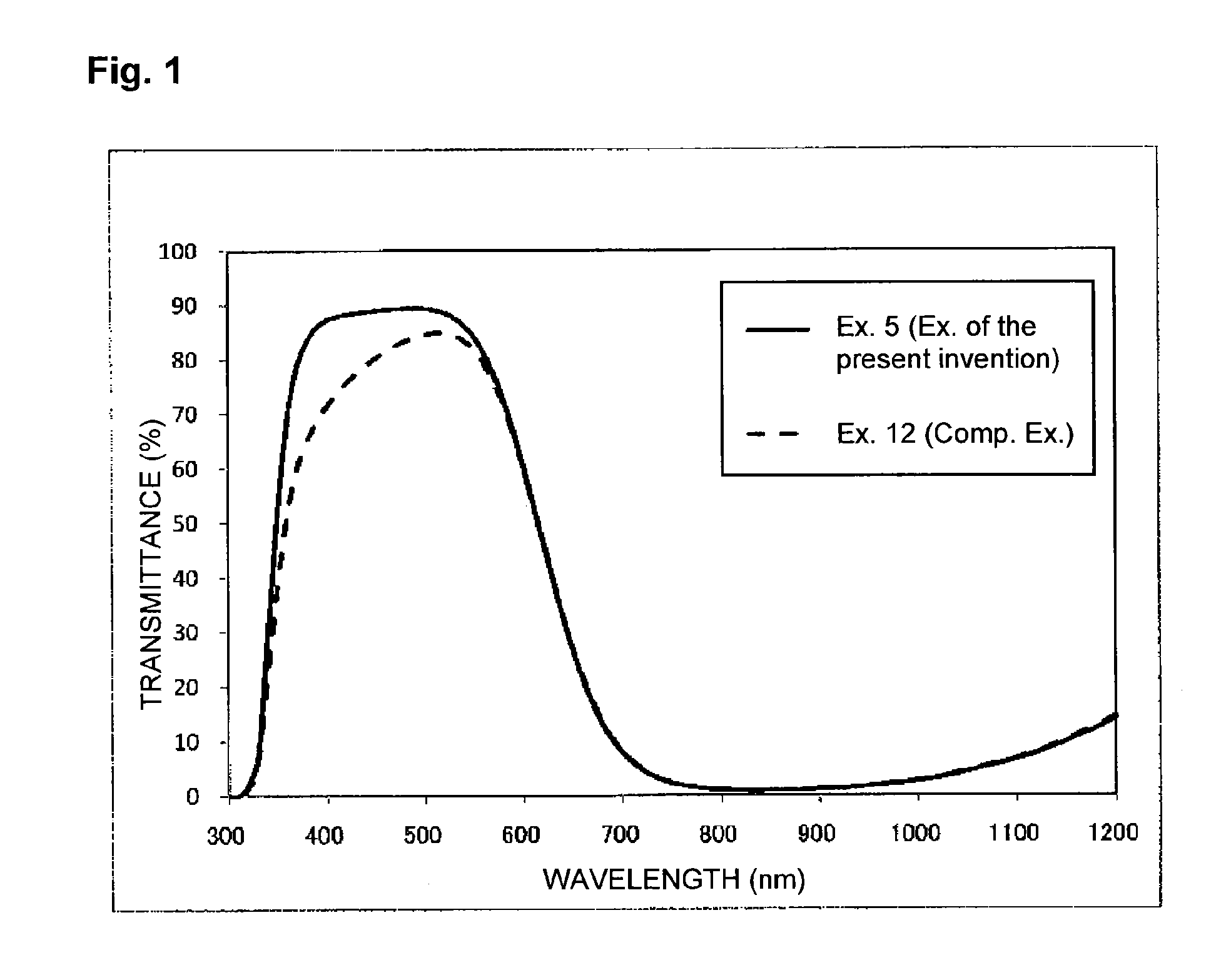
[0056]Now, the present invention will be specifically described with reference to Examples, but the technical scope of the present invention is by no means limited to these Examples.

[0057]Various types of glass materials were weighed and mixed according to the mass percentage values as calculated as those of compounds of Tables 1 and 2. The raw material mixture was put in a platinum crucible, capped and heated at a temperature of 900° C. in an electric furnace. It was sufficiently stirred and refined, and thereafter, casted in a mold and annealed. Thereafter, it was cut and polished to produce a plate having a size of 50 mm×200 mm×2 mm thick. The plate was disposed in a stretching apparatus, heated to the vicinity of softening point and stretched to produce a thin plate having a thickness of 0.15 mm.

[0058]Examples of the present invention and Comparative Examples are shown in Tables 1 and 2. Here, Examples 1 to 10 are Examples of the present invention, and Examples 11 to 15 are Comp...


PUM

PropertyMeasurementUnit
Fractionaaaaaaaaaa
Fractionaaaaaaaaaa
Fractionaaaaaaaaaa

Abstract

The present invention provides a process for producing a near infrared cut filter glass by melting and forming a glass material blended; and from 0.1 to 5% as represented by mass percentage of an oxidant of at least of a nitrate compound, a sulfate compound, a peroxide, a perchlorate and chloric acid as well as a near infrared cut filter glass.

Description

TECHNICAL FIELD[0001]The present invention relates to a near infrared cut filter glass which is used as a luminosity factor correction filter for a digital still camera attached to a cellular phone or a compact type digital still camera, which efficiently transmits a visible light having a wavelength of from 400 to 600 nm, and which is excellent in a sharp cut characteristic of near infrared light in the vicinity of a wavelength of 700 nm, and to a process for producing such a near infrared cut filter glass.BACKGROUND ART[0002]A solid-state image-capturing element such as CCD or CMOS to be used for a digital still camera attached to a cellular phone or a compact type digital still camera, has a spectral sensitivity of from visible region to a near infrared region in the vicinity of 1,100 nm. Accordingly, it is not possible to obtain a good color reproducibility as it is, and it is necessary to correct the luminosity factor by a filter cutting light in the near infrared region.[0003]...

Claims


Application Information

Patent Timeline
IPC IPC(8): G02B5/20
CPCC03C4/082G02B5/223G02B5/208C03C3/247C03C1/00
Inventor SUZUKI, HIDETOSHI
Owner ASAHI GLASS CO LTD
Learn More