Wave energy converter

a technology of wave energy and converter, which is applied in the direction of machines/engines, water-power plants, positive displacement liquid engines, etc., can solve the problems of affecting the operation of devices, so as to achieve the effect of optimizing the generation of power

Inactive Publication Date: 2005-04-21
ZADIG STEPHEN J
View PDF14 Cites 44 Cited by
  • Summary
  • Abstract
  • Description
  • Claims
  • Application Information

AI Technical Summary

Benefits of technology

[0006] One advantage of the invention is that it provides a wave energy converter that is designed to utilize the force of gravity as a primary component of power generation.
[0007] Another advantage of the invention is that it provides a wave energy converter that is selectively and dynamically adjustable to optimize the generation of power based on the current status of wave and / or swell activity.
[0008] According to a first aspect of the present invention, a wave energy converter is provided and includes a support structure fixed to a floor of a body of water; a piston assembly including a housing that forms a chamber containing an amount of pressurized fluid and having a first end attached to the support structure and a second end, a piston that is slidably disposed within the chamber, and a piston rod that is attached to the piston and that extends from the second end of the housing; a buoyant floatation device that is attached to the piston rod and that is adapted to cause the piston to move upward in the chamber in response to a rising wave, and to move downward by the force of gravity in response to a falling wave, the downward motion and gravitational force being effective to discharge the pressurized fluid from the chamber; and a hydraulically driven power generator that receives the discharged pressurized fluid from the chamber, and utilizes the pressurized fluid to generate electrical power or for other applications, such as desalination.
[0009] According to a second aspect of the present invention, a wave power generator is provided and includes a support structure fixed to a floor of a body of water, the support structure including a pair of telescoping members that are movable relative to each other, effective to adjust a length of the support structure; a hydraulic assembly that is operatively coupled to the support structure and adapted to cause the telescoping members to move relative to each other, thereby adjusting the length of the support structure; a hydraulic piston assembly that is attached to the support structure and that contains an amount of pressurized fluid; a buoyant floatation device that is attached to the hydraulic piston assembly and that is adapted to move upward in response to a rising wave and downward under the force of gravity in response to a falling wave, the downward motion being effective to discharge pressurized fluid from the hydraulic piston assembly; a hydraulically driven power generator that receives the discharged pressurized fluid from the chamber, and utilizes the pressurized fluid to generate electrical power; and a control system that is communicatively coupled to the hydraulic assembly and that is adapted to monitor water conditions and to cause the hydraulic assembly to dynamically adjust the length of the support structure based on the monitored water conditions.
[0010] According to a third aspect of the present invention, a method for converting energy from waves formed in a body of water is provided. The method includes steps of: providing a floatation device that is adapted to move upward in response to a rising wave and downward under the force of gravity in response to a falling wave; and utilizing the downward motion and gravitational force of the floatation device to drive fluid through a hydraulically driven power generator, thereby generating electrical power. The floatation device may be attached to a hydraulic piston assembly containing fluid, such that the downward motion of the floatation device actuates the piston assembly, thereby driving the fluid through the hydraulically driven power generator. The piston assembly may be supported at a certain height above a bottom of the body of water. The method may further include the steps of monitoring water conditions; and selectively adjusting the certain height based upon the monitored water conditions; and / or controlling the flow of fluid through the hydraulically driven power generator based upon the monitored water conditions.
[0011] These and other aspects, features, and advantages of the present invention will become apparent from a consideration of the following specification and the attached drawings.

Problems solved by technology

Although offshore generators may provide a greater amount of energy, they suffer from some drawbacks.
For instance, because of the increased size and power of offshore waves, the construction of these devices is more difficult and complex.
Furthermore, these devices are typically unable to dynamically adjust their operation to optimize power generation based upon water conditions.
Additionally, these devices typically rely only on the rising crests of waves and / or in the resulting changes in pressure to generate electricity, and do not utilize the force of gravity.

Method used


Image

  • Wave energy converter
  • Wave energy converter
  • Wave energy converter

Examples


Embodiment Construction

[0018] The present invention will now be described in detail with reference to the drawings, which are provided as illustrative examples of the invention so as to enable those skilled in the art to practice the invention. Where certain elements of the present invention can be partially or fully implemented using known components, only those portions of such known components that are necessary for an understanding of the present invention will be described, and detailed descriptions of other portions of such known components will be omitted so as not to obscure the invention. Embodiments of the present invention are illustrated in the Figures, like numerals being used to refer to like and corresponding parts of various drawings.

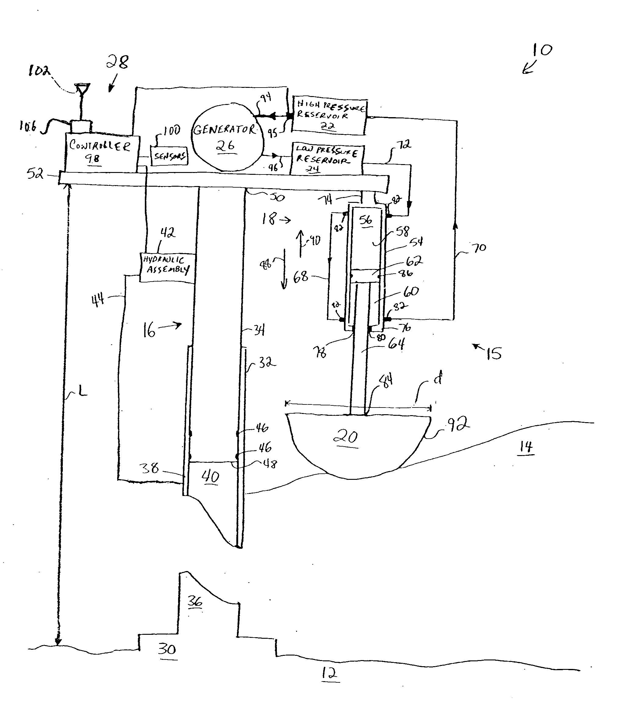
[0019] Referring now to FIG. 1, there is shown one embodiment of a wave power generator 10 that is made in accordance with present invention and that is adapted for use in offshore and deep-sea locations. Wave power generator 10 is adapted for secure attachme...


PUM


Abstract

An improved wave energy converter for use in offshore and deep-sea locations. The wave energy converter is adapted for secure attachment to the bottom of a body of water (e.g., the ocean floor), preferably beyond the breaker zone. The wave energy converter is selectively adjustable in length. A hydraulic power generation system is used to convert the energy present in the waves into hydraulic power that can be use to generate electricity and for other purposes, such as desalinization. The system may include a hydraulic piston assembly, a floatation device that is connected to the piston assembly, high and low pressure hydraulic reservoirs, and a hydraulically driven power generator. The floatation device moves upward in response to rising waves, and downward under the force of gravity in response to falling waves. The system utilizes this downward gravitational force to discharge fluid from the piston assembly, which in turn, drives the power generator. A control system is used to detect water conditions and to selectively adjust the length of the support structure and the fluid flow characteristics to dynamically optimize power generation based on changing water conditions.

Description

FIELD OF THE INVENTION [0001] This invention generally relates to a wave energy converter and more particularly, to a wave power generator that utilizes gravity as a primary component in the generation of hydraulic energy, which can be used to generate electrical power, and that is selectively adjustable to optimize power generation based upon water conditions. BACKGROUND OF THE INVENTION [0002] Waves contain a large amount of energy, which if converted into electricity, can help serve the world's increasing demands for electrical power. Many attempts have been made to harness the energy contained in waves and convert that energy into electrical power. These attempts include shoreline type generators, which are constructed at or near the shoreline, and offshore generators, which are constructed beyond the breaker zone and / or in the deep sea. Shoreline generators are generally easier to construct, but produce less energy than offshore generators, which are able to capture the greater...

Claims


Application Information

Patent Timeline
Patent Type & Authority Applications(United States)
IPC IPC(8): F03B13/18F04B5/02F04B17/00
CPCF03B13/187Y02E10/38F04B17/00F04B5/02Y02A20/144Y02E10/30
Inventor ZADIG, STEPHEN J.
Owner ZADIG STEPHEN J
Why Eureka
Try Eureka