Tube-coated belt, heat fixing apparatus, and organopolysiloxane adhesive composition
- Summary
- Abstract
- Description
- Claims
- Application Information
AI Technical Summary
Benefits of technology
Problems solved by technology
Method used
Image
Examples
examples
[0152] The present invention will be specifically described below referring to Examples and Comparative Examples; however, the present invention is not limited thereto. Unless otherwise specified, commercially available high-purity reagents and the like were used. The viscosities described herein are values measured at 25° C. using RotoVisco RV1 (trade name), a precision rotary viscometer manufactured by EKO INSTRUMENTS Co., Ltd., and the parts are indicated by parts by weight.
(Evaluation of Thermal Conductivity of Silicone-Rubber Elastic Layer)
[0153] A silicone-rubber material composition was heat-molded to prepare a plate-like test piece of a thickness of 10 mm, and the thermal conductivity thereof was measured using a quick thermal conductivity meter QTM-500 (trade name of Kyoto Electronics Manufacturing Co., Ltd.).
(Evaluation of Performance of Heat-Fixing Apparatus and Fixation Belt)
[0154] Recording materials carrying cyan toner images before fixation were passed through t...
examples 1 to 24
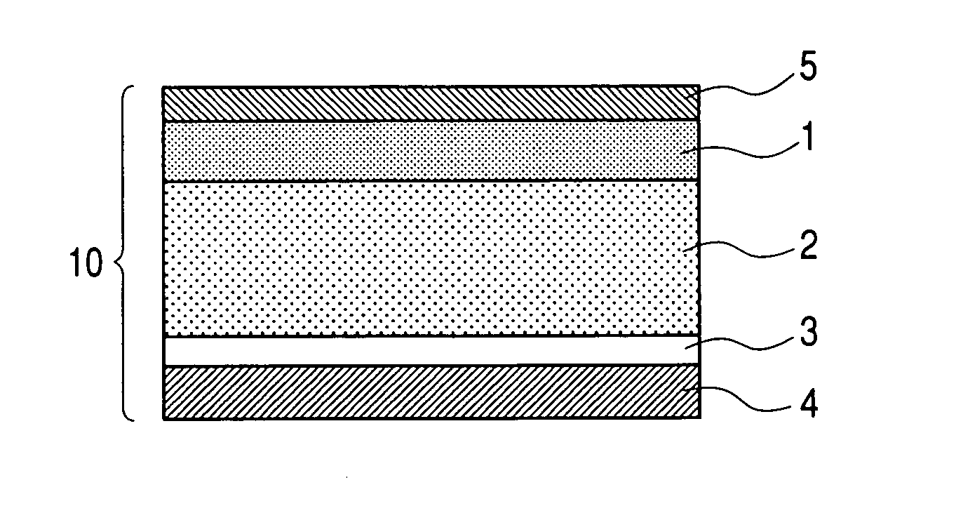
[0175] An electroformed nickel endless belts having inner diameters of 24 mm and 30 mm and a thickness of 35 μm shown in Table 1 was used as belt-like base layers; and a silicone-rubber material composition obtained by compounding and kneading the quantities shown in Table 1 of magnesium oxide (pyrokisuma 3320, trade name of Kyowa Chemical Industry Co., Ltd.) as a thermal conductivity imparting agent in 100 parts by weight (solid content) of an additive silicone rubber (DY35-561A / B, trade name of Dow Corning Toray Sillicone Co., Ltd.) was used as a silicone-rubber material composition for forming silicone-rubber elastic layers. This silicone-rubber material composition was applied to the belt-like base layer using a ring coating method, and cured to form silicone-rubber elastic layers.
[0176]FIG. 4 is a schematic diagram of the ring coat method. A coating table 442 capable of horizontally and pivotally rotating an aluminum cylinder holding tool 411 having a belt-like base layer 441 ...
example 25
[0197] A nickel electrocast belt having an inner diameter of 34 mm and a thickness of 50 μm was used as a belt-shaped base layer, and a silicone rubber raw material composition similar to that of Example 1 was used as a silicone rubber raw material composition for formation of a silicone rubber elastic layer. This silicone rubber raw material composition was coated on the belt-shaped base layer using the ring coat method, and thermally cured at 200° C. for 4 hours to form a silicone rubber elastic layer having a thickness of 300 μm.
[0198] Next, an organopolysiloxane adhesive composition (Adl) was prepared in the same manner as in Examples 1 to 24. It comprised 50 parts of a polydimethylsiloxane with a dimethyl vinyl siloxy terminal, having a viscosity of 3000 Pa.s (sometimes referred to as a11) as Component (A); 50 parts of a resinous organopolysiloxane comprising a CH2═CH(CH3)2SiO1 / 2, (CH3)3SiO1 / 2 and SiO4 / 2 units, molar ratio of the CH2═CH(CH3)2SiO1 / 2 and (CH3)3SiO1 / 2 units total...
PUM
| Property | Measurement | Unit |
|---|---|---|
| Percent by mass | aaaaa | aaaaa |
| Percent by mass | aaaaa | aaaaa |
| Percent by mass | aaaaa | aaaaa |
Abstract
Description
Claims
Application Information
 - R&D
- Intellectual Property
- Life Sciences
- Materials
- Tech Scout
- Unparalleled Data Quality
- Higher Quality Content
- 60% Fewer Hallucinations
Browse by: Latest US Patents, China's latest patents, Technical Efficacy Thesaurus, Application Domain, Technology Topic, Popular Technical Reports.
© 2025 PatSnap. All rights reserved.Legal|Privacy policy|Modern Slavery Act Transparency Statement|Sitemap|About US| Contact US: help@patsnap.com


