
Pouch type secondary battery

a secondary battery, a pouch type technology, applied in the field of pouch type secondary batteries, can solve the problems of corner corrosion, electric short circuit, and interference with the external pack used for packaging, and achieve the effect of preventing an electrical short circuit and corrosion acceleration of the core material

Active Publication Date: 2005-04-21
SAMSUNG SDI CO LTD
View PDF5 Cites 49 Cited by
  • Summary
  • Abstract
  • Description
  • Claims
  • Application Information

AI Technical Summary

Benefits of technology

The present invention provides a pouch type secondary battery with enhanced safety. It prevents electrical short circuits and corrosion acceleration of the battery core materials. The battery includes an electrode assembly with electrode plates and a separator, a flexible pouch case made of insulating material, and sealing portions. The sealing portions include first and second sealing portions through which electrode taps extend from the pouch case. A short circuit protector is connected to the electrodes and mounted on the outer surface of the first sealing portion. The short circuit protector may be a folded portion of the sealing portion or an insulating tape. The invention also provides a pouch type secondary battery with a protective circuit module and a folded sealing portion that prevents electrical short circuits and corrosion acceleration.

Problems solved by technology

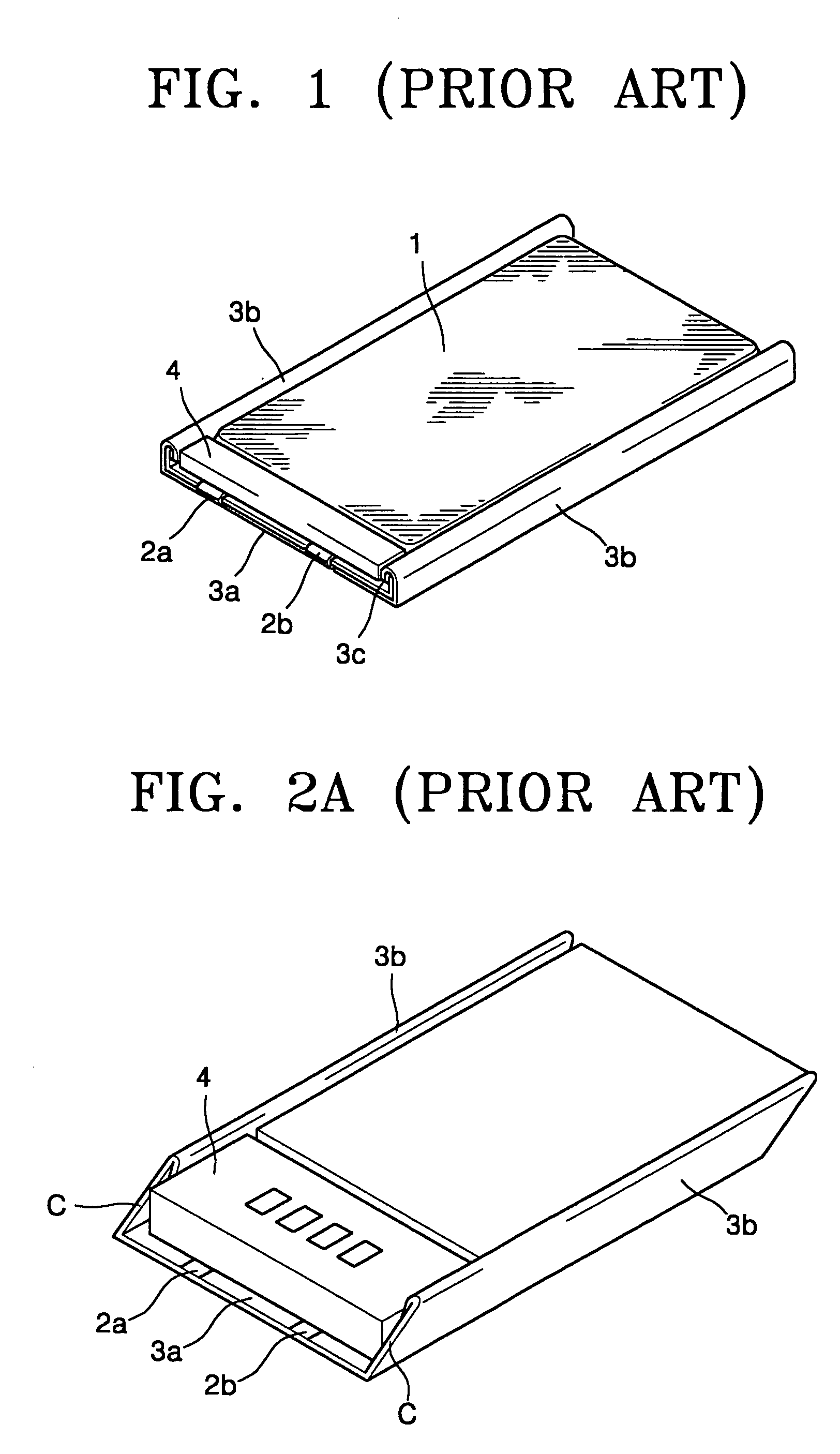
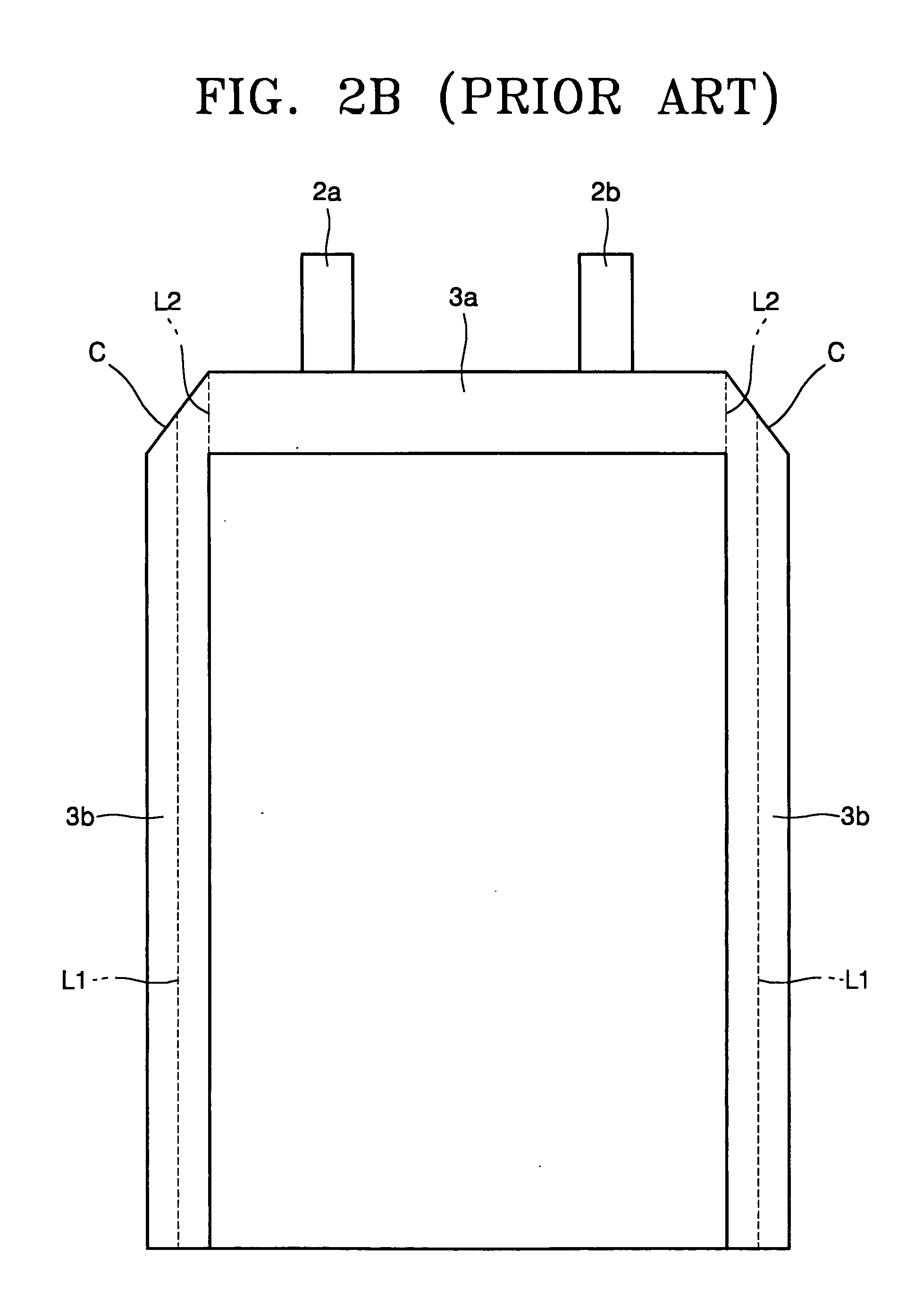
However, since a corner 3c of the sealing portions 3a and 3b protrudes outward, the corner 3c may interfere with an external pack used for packaging.
This contact may cause an electric short circuit of a module of the protective circuit board 4 and also accelerate the corrosion of the corner 3c.
These problems occur more frequently when the corner 3c is crushed by an external pack.
In other words, this second battery cannot overcome the problems described above with reference to FIG. 1.

Method used


Image

  • Pouch type secondary battery
  • Pouch type secondary battery
  • Pouch type secondary battery

Examples


Embodiment Construction

[0060] Reference will now be made in detail to the embodiments of the present invention, examples of which are illustrated in the accompanying drawings, wherein like reference numerals refer to the like elements throughout. The embodiments are described below to explain the present invention by referring to the figures.

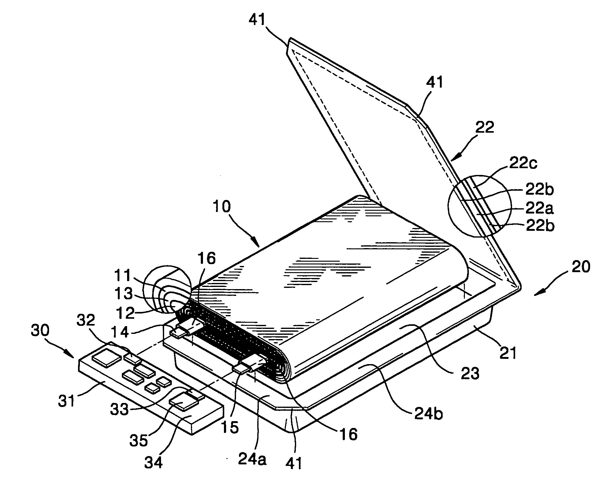
[0061]FIG. 3 is an exploded perspective view of a pouch type secondary battery according to an embodiment of the present invention. FIGS. 4 through 6 are perspective, plane, and partial side views, respectively, of the pouch type secondary battery shown in FIG. 3.

[0062] As shown in FIGS. 3 through 6, the pouch type secondary battery according to an embodiment of the present invention includes an electrode assembly 10, in which a separator 13 is interposed between a first electrode plate 11 and a second electrode plate 12, and a pouch case 20 accommodating the electrode assembly 10. The electrode assembly 10 may be implemented by an electrode jelly role or a stack ty...


PUM

PropertyMeasurementUnit
internal pressureaaaaaaaaaa

Abstract

A pouch type secondary battery which can prevent a cut portion from electrically contacting a protective circuit module, thereby preventing an electrical short circuit and acceleration of corrosion of a core material and enhancing safety includes an electrode assembly having a first electrode plate, a second electrode plate, and a separator; a pouch case made of a flexible material, and having a container, insulated at least on its inner surface and accommodating the electrode assembly, and sealing portions along an edge of the container, the sealing portions including a first sealing portion through which electrode taps of the electrode assembly extend from the pouch case, and a second sealing portion and a third sealing portion respectively positioned at opposite sides of the first sealing portion, the second an third sealing portions being folded at least one time; a protective circuit module connected to the electrode taps and mounted on an outer surface of the first sealing portion; and a short circuit protector formed in at least one among the first through third sealing portions to prevent an electrical short circuit between each sealing portion and the protective circuit module.

Description

CROSS-REFERENCE TO RELATED APPLICATIONS [0001] This application claims the benefit of Korean Patent Application No. 2003-72155, filed on Oct. 16, 2003, in the Korean Intellectual Property Office, the disclosure of which is incorporated herein by reference. BACKGROUND OF THE INVENTION [0002] 1. Field of the Invention [0003] The present invention relates to a secondary battery, and more particularly, to a pouch type secondary battery having a pouch case with an improved structure. [0004] 2. Description of the Related Art [0005] Secondary batteries are rechargeable. They can be made small and have a large capacity. Representative secondary batteries are nickel-metal hydride (Ni—MH) batteries and lithium (Li) secondary batteries. [0006] According to the type of a case accommodating an electrode assembly, secondary batteries can be divided into cylindrical batteries using a cylindrical aluminum can, prismatic batteries using a prismatic aluminum can, and pouch type batteries using a thin...

Claims


Application Information

Patent Timeline
Patent Type & Authority Applications(United States)
IPC IPC(8): H01M6/50H01M10/04H01M10/34H01M50/105H01M50/186H01M50/55H01M50/557
CPCH01M2/0202H01M2/0212H01M2/08H01M2/1241Y10T29/4911H01M10/052H01M10/0585H01M10/345H01M2200/00H01M10/0436Y02E60/10H01M50/557H01M50/3425Y02P70/50H01M50/105H01M50/186H01M50/55
Inventor HWANG, IN-WONLEE, HYUNG-BOKKIM, JOONG-HUNCHOL, JAE-HOON
Owner SAMSUNG SDI CO LTD
Learn More