Battery management system and method

a battery management system and battery technology, applied in the field of power supply systems, can solve problems such as the inability to support higher power functions

Active Publication Date: 2005-04-21
MALIKIE INNOVATIONS LTD
View PDF17 Cites 79 Cited by
  • Summary
  • Abstract
  • Description
  • Claims
  • Application Information

AI Technical Summary

Problems solved by technology

If battery charge is low, the mobile communication device may be able to s

Method used


Image

  • Battery management system and method
  • Battery management system and method
  • Battery management system and method

Examples


Embodiment Construction

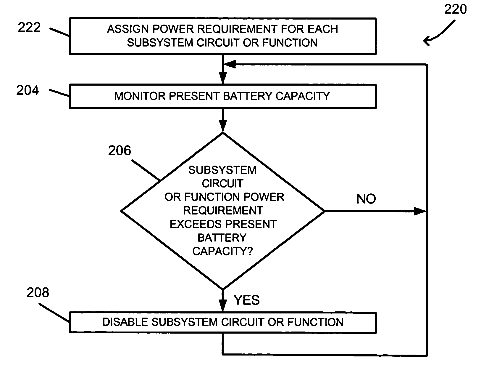
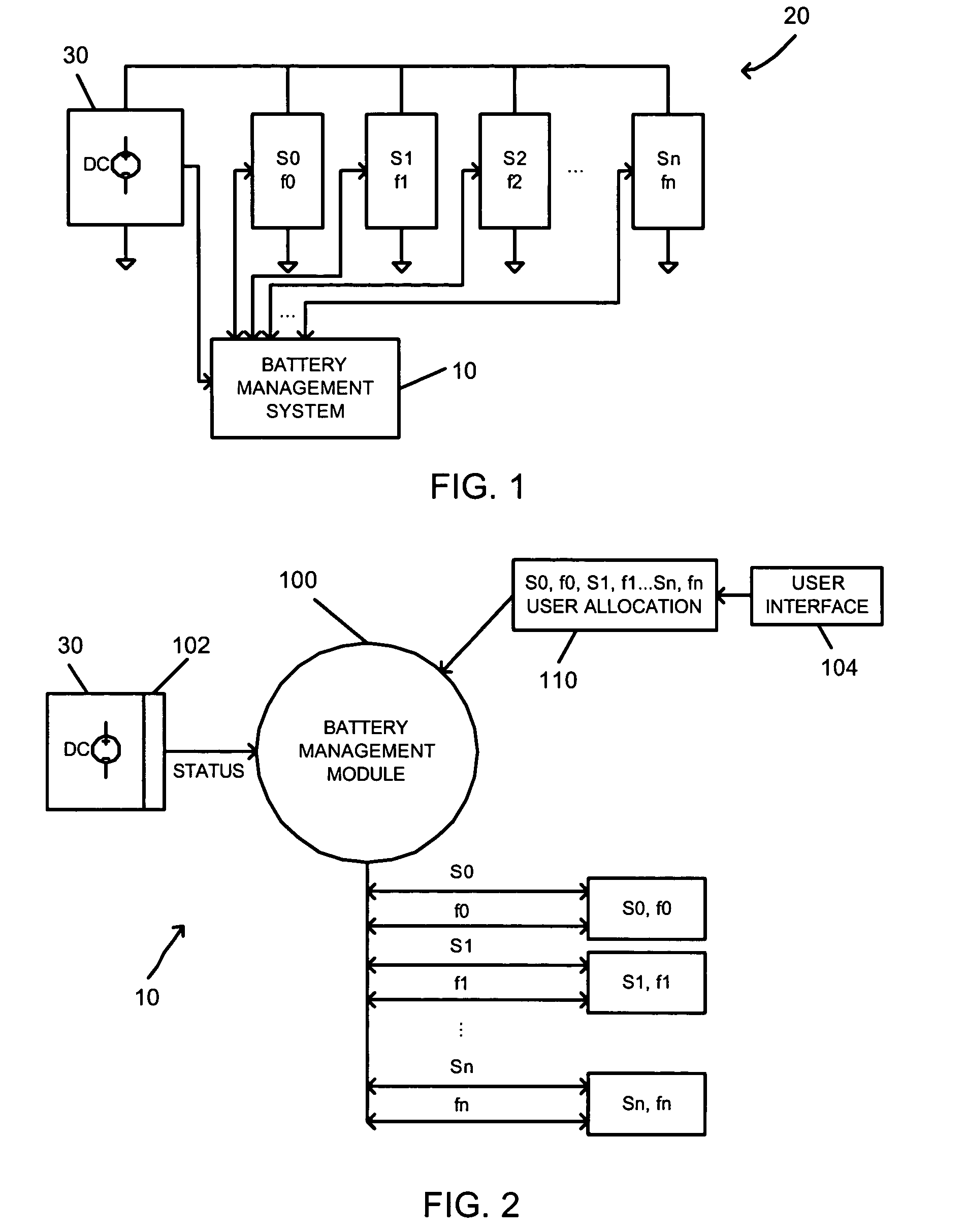
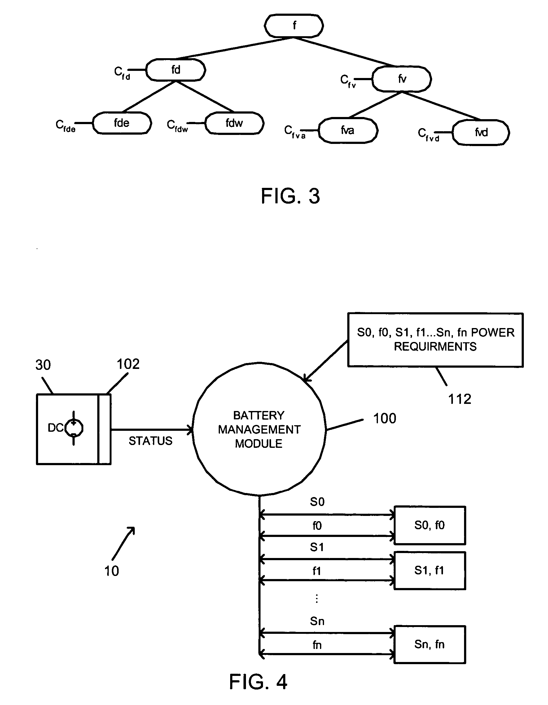
[0023]FIG. 1 is a block diagram of a battery management system 10 in a mobile communication device 20. The mobile communication device 20 illustratively comprises a power subsystem 30 and a plurality of subsystem circuits S0, S1, S2 . . . Sn. Each subsystem circuit S0, S1, S2 . . . Sn supports a corresponding function set f0, f1, f2 . . . fn. The mobile communication device 20 may be realized by a data messaging device, a two-way pager, a cellular telephone with data messaging capabilities, a wireless Internet appliance, or other data communication devices, depending on the functionality provided. An exemplary mobile communication device 20 is described in detail with reference to FIG. 13 below.

[0024] Each function set may include common functions. Thus, one or more subsystem circuits S0, S1, S2 . . . Sn may be activated to support a corresponding common function. For example, if the mobile communication device 20 is a cellular telephone with Internet connectivity, a voice function...


PUM


Abstract

A battery management system for managing a plurality of subsystem circuits and functions of a mobile communication device powered by a battery is disclosed. The battery management system includes a battery monitoring circuit, a user interface, and a battery management module. The battery monitoring circuit is operable to monitor a present battery capacity and generate a battery capacity signal based on the present battery capacity. The user interface is operable to receive a user-input allocation of battery capacity among the subsystem circuits and functions. The battery management module is operable to receive the user-input allocation and the battery capacity signal, and to selectively disable each subsystem circuit or function when each subsystem circuit or function has depleted its allocation of battery capacity.

Description

BACKGROUND [0001] 1. Field of the Invention [0002] The invention relates generally to power supply systems, and in particular to a battery management system in a mobile communication device. [0003] 2. Description of the Related Art [0004] A typical mobile communication device is powered by a rechargeable battery. However, the same mobile communication device may also include several subsystem circuits, such as input / output (I / O) circuits, wireless communication circuits, processing circuits, and the like, to support such device functions as voice communication functions and data communication functions. [0005] Each device function may be supported by one or more subsystem circuits. The activity period of a subsystem circuit varies according to the function activated at the mobile communication device. Thus, power requirements may vary significantly among device functions, due to differences among the subsystem circuits supporting each function and the activity periods of each subsys...

Claims


Application Information

Patent Timeline
IPC IPC(8): G06F1/32H04M1/73
CPCG06F1/3215H04W52/0261G06F1/3212H04W52/0277Y02B60/1292H04W52/0264Y02D10/00Y02D30/70
Inventor CHEN, JOSEPH C.MALTON, JONATHAN
Owner MALIKIE INNOVATIONS LTD
Why Eureka
Try Eureka