The above characteristics and features specific to invasive products make them much more expensive and complicated to design and manufacture than conventional diagnosing devices.
In
spite of the use therein of dual transducers, rotating transducers and 2D array transducers, invasive ultrasonic devices still suffer a number of drawbacks and shortcomings with regard to complexity of design, cost of manufacturing and / or lack of reliability.
However, the sophistication added to conventional TEE probes has not only enhanced the performance and operating characteristics of the
resultant probe but has also raised considerably the manufacturing costs of the probe while simultaneously decreasing the reliability thereof in operation, thereby dramatically increasing the maintenance costs associated with the probe.
It is also noted that endocavity probes that are commonly provided with basic
phased array transducers or dual
transducer mountings suffer certain limitations in terms of scanning range and the
angle of view available during examination.
However, mechanical sector moving
transducer probes are much less common than other the types and the trend is toward electronic scanning devices having a single or dual static transducer array.
The drawbacks of such devices principally concern the
crowding or encumbrance of the transducer tip portion produced by mounting several array transducers in close proximity, the complexity of the transducer housing and the complexity or intricacy involved in mounting the
assembly onto the probe.
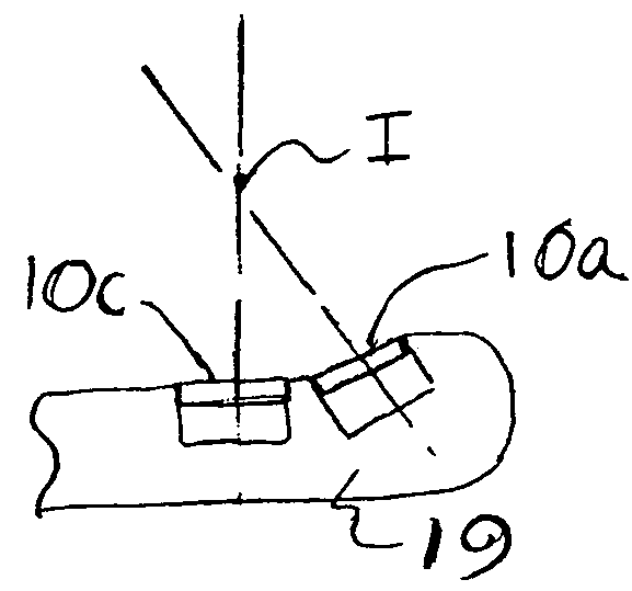
Further, the transducers are not located in the same area so that the intersecting zone or region can only be achieved at a certain distance with respect to the emission surfaces of the transducers, thus preventing exploitation of the near field of the image.
The alternate rotation of the transducer during the operation thereof is a source of electrical
noise or contact wear.
Further, the high degree of integration that the device exhibits results in an increase in cost and a lack of reliability.
However, 2D array transducers provide a scanning
image quality that is much lower than that obtained with a 1D
phased array, and the complexity involved in addressing all elements of such an array would make the device unattractive for many applications.
In conclusion with respect to these types of prior art transducers, whether incorporated in TEE or endo-cavity probes including intravascular and intracardiac devices,
current transducer implementation methods such as aforementioned still impose on manufacturers and users a number of constraints that limit the scanning possibilities of the probes and / or considerably increase the manufacturing cost thereof and, furthermore, reduce the reliability of the
resultant probe devices.
Such a transducer has been disclosed in prior art with a number of different variations in the design and construction thereof but the transducer is still difficult to implement in practice and the acoustic performance thereof is limited by the lack of efficient isolation between the first and the second arrays as well as between the elements of the same array.
However, this early conception cannot be considered to be a true bi-plane construction because the second array of the apparatus is very different from the first array and serves in carrying out Doppler functions or positioning operations.
However, it is noted that no
interconnection method is disclosed in these patents and the grooving method described therein limits the cross
coupling performance of the transducers.
As a result of constructions described above, the bi-plane transducers as disclosed in the Slayton et al. patent suffer several limitations with respect to their manufacture and operation.
In this regard, for the crossed section type, both of the arrays suffer from a substantial
diminution of the element surface at the center area of the transducer which results in a dramatic loss of sensitivity at the middle portion of the image (or even the absence of an image at the center of the display).
This is unacceptable in diagnostic applications and thus such a transducer construction simply cannot be used in clinical applications.
The complexity involved in manufacturing and assembling such a device is greater than that discussed above for standard 2D arrays so that a cost effective implementation of such an array, and the associated addressing
electronics, in an invasive
medical product is difficult to practically achieve.
In summary, while currently available invasive
ultrasound products which still use rotating
phased array arrangements or separate phased array assemblies suffer significant disadvantages, a bi-plane approach has not been viable for important applications because of difficulties associated with making bi-plane transducers as well as the lack of a viable technical solution with respect to the problem of integrating such a bi-plane transducer into an invasive probe.

