Data transfer system, data transfer program and video server system

a data transfer system and data transfer program technology, applied in the data field, can solve the problems of not necessarily equal storage capacity of the two storage media, and the processing capability of the two different systems to control the same storage medium,

Active Publication Date: 2005-04-21
PANASONIC CORP
View PDF3 Cites 27 Cited by
  • Summary
  • Abstract
  • Description
  • Claims
  • Application Information

AI Technical Summary

Benefits of technology

[0012] In order to overcome the problems described above, preferred embodiments of the present invention provide an data transfer system and program and a video server system, which can reconstruct original HD data even if down-converted data once moved is returned to its original location.

Problems solved by technology

However, the storage capacities of the two storage media, between which the data should be moved, are not necessarily equal to each other.
Nor are the processing capabilities of the two different systems to control the same storage medium, either.
For example, a DVD drive does not support digital audiovisual data of a high definition (HD) resolution.
However, the user should know that the DVD drive cannot accept data of such a high resolution.
Nevertheless, if the user wanted to play back the digital audiovisual data, which has now moved to the DVD, at the original HD resolution again, then that should be a problem.
That is to say, in the prior art, once digital audiovisual data has been down converted as a result of a move, that digital audiovisual data can never be played back at the original resolution.

Method used


Image

  • Data transfer system, data transfer program and video server system
  • Data transfer system, data transfer program and video server system
  • Data transfer system, data transfer program and video server system

Examples


embodiment 1

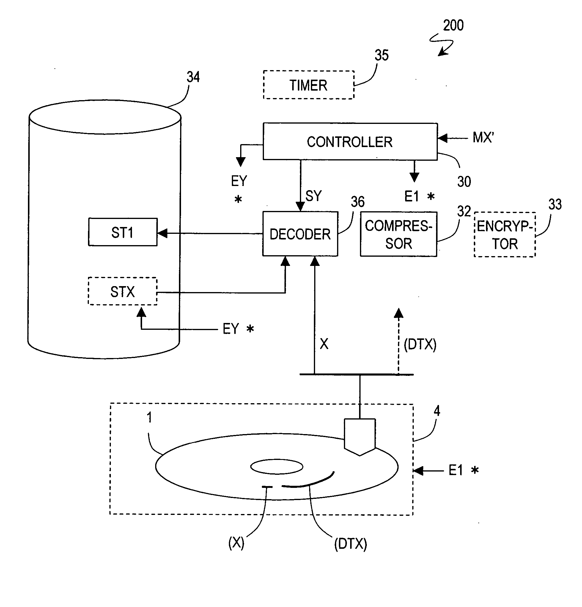
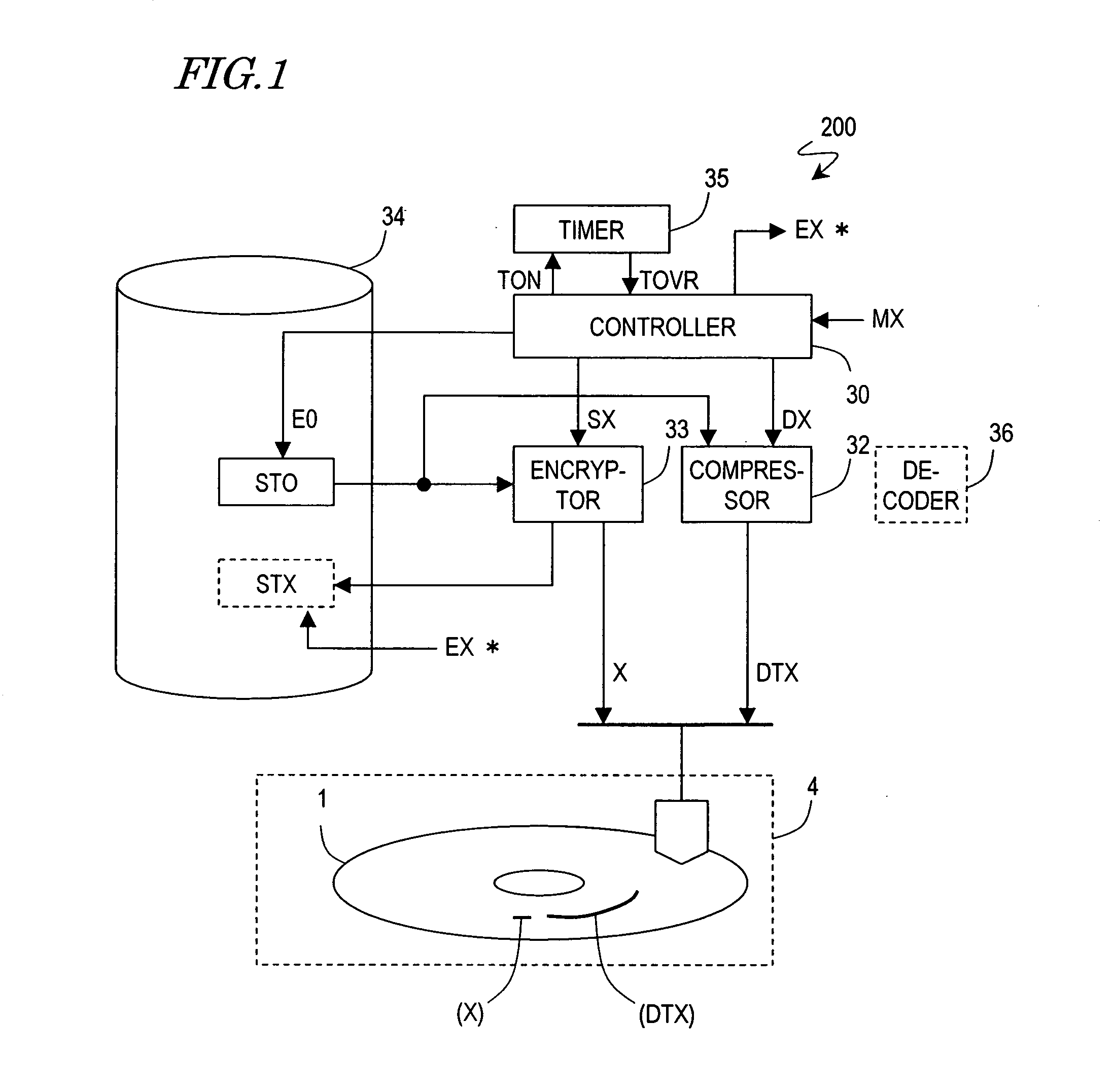
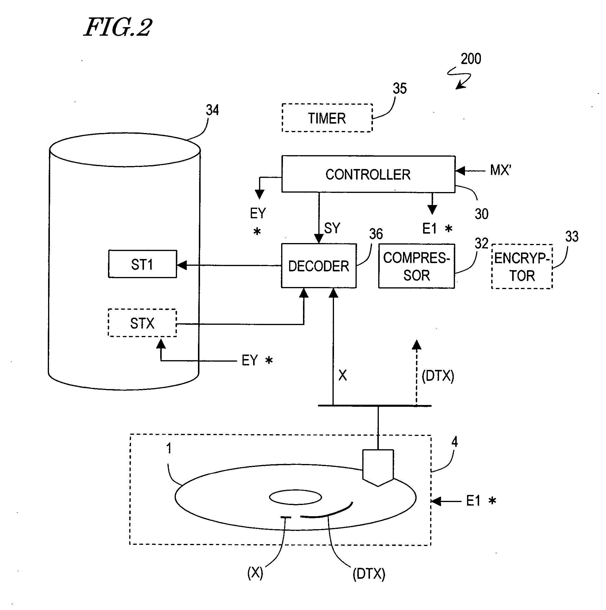
[0039]FIG. 1 is a block diagram showing a configuration for a data transfer system 200 according to a first specific preferred embodiment of the present invention. The data transfer system 200 may receive data from a first data storage device 34 and transfer it to a second data storage device 4. The first data storage device 34 may be a hard disk drive or the like, for example, and preferably has a relatively large storage capacity. On the other hand, the second data storage device 4 may be an optical disk drive with an optical disk, a memory card with a nonvolatile memory, or a hard disk drive with a relatively small storage capacity. In this preferred embodiment, the second data storage device 4 is supposed to be an optical disk drive. In any case, the first and second data storage devices 34 and 4 are preferably able to at least write data on a storage medium and protect the stored data such that the data can neither be erased nor read. As used herein, to “erase data” means makin...

embodiment 2

[0060]FIG. 4 is a block diagram showing a configuration for a video server system 300 according to a preferred embodiment of the present invention. The video server system 300 includes servers 10 and 13, which are connected together over a network 100 so as to establish a telecommunications link between them. In the example shown in FIG. 4, in accordance with an instruction issued by the server 10, the server 13 receives a broadcast program and transmits the audiovisual data of the broadcast program to the server 10 over the network 100. In this video server system 300, each component having the same function as the counterpart of the data transfer system 200 of the first preferred embodiment described above is identified by the same reference numeral. As shown in FIG. 4, the server 10 includes a controller 3 and the second data storage device 4, while the server 13 includes the controller 30, the compressor 32, the encryptor 33, the first data storage device 34 and a tuner 131.

[00...


PUM

PropertyMeasurementUnit
timeaaaaaaaaaa
sizeaaaaaaaaaa
keeping timeaaaaaaaaaa

Abstract

A data transfer system transfers original data from a first data storage device to a second data storage device. The transfer system includes a compressor, an encryptor, and a controller. The compressor receives the original data from the first data storage device, generates compressed data of a smaller size, and passes the compressed data to the second data storage device. The encryptor makes a predetermined cryptographic key and passes the key to the second data storage device. The encryptor also receives the original data from the first data storage device, encrypts the original data with the cryptographic key and then sends the encrypted data back to the first data storage device. The controller controls the compressor and the encryptor and gives the first data storage device a first erase instruction, telling the first data storage device to erase the original data, in accordance with a first transfer command.

Description

BACKGROUND OF THE INVENTION [0001] 1. Field of the Invention [0002] The present invention relates to a distributed video server system constructed by connecting together a plurality of video recorders, each including an optical disk recorder, through a network. [0003] 2. Description of the Related Art [0004] Recently, videocassette recorders, which used to be dominating consumer audiovisual equipment, are gradually being replaced by optical disk recorders, which use a disk storage medium such as a recordable or rewritable DVD (which will be referred to herein as an “optical disk”) to read and write audiovisual data therefrom / thereon by an optical technique. The optical disk has a planar data storage layer on which digital audiovisual data is stored. In performing a read or write operation on such an optical disk, an optical head can access any arbitrary location on the data storage layer in a matter of seconds. Accordingly, even if multiple titles of video data are stored on the sam...

Claims


Application Information

Patent Timeline
Patent Type & Authority Applications(United States)
IPC IPC(8): G06F12/14G11B20/10H04N5/781H04N5/85
CPCG11B20/00007G11B20/00086G11B2220/40G11B20/00282G11B20/00666G11B20/0021
Inventor ISHIBASHI, HIROMICHIKOMMA, YOSHIAKI
Owner PANASONIC CORP
Why Eureka
Try Eureka