Light pipe illumination system and method

a technology of illumination system and light pipe, applied in the field of illumination, can solve the problems of obscuring the acquired image, affecting the processing speed, and inability to use highly reflective bright field illumination, and achieve the effect of facilitating better aiming of the sensor

Inactive Publication Date: 2005-04-28
COGNEX TECH & INVESTMENT
View PDF98 Cites 163 Cited by
  • Summary
  • Abstract
  • Description
  • Claims
  • Application Information

AI Technical Summary

Benefits of technology

[0009] This invention overcomes the disadvantages of the prior art by providing a system and method for illuminating a subject using a light pipe that transmits light from a source, such as an LED ring illuminator to an outlet that directs the light appropriately as either bright field illumination, dark field illumination or both. The light pipe can include concentric or coaxial (nested) cylinders, typically with a bright field illuminator nested within a dark field illuminator. The tip of the dark field illuminator is angled so as to internally reflect light inwardly toward the central optical axis of a camera at a low angle. The tip can be located near the focal plane of the camera for the desired field of view. The field of view of the camera sensor can be modified to reject data outside of a illumination field of a particular shape. This illumination field can be created by shaping the light pipe in a predetermined form that projects the modified illumination field. Likewise, a set of aiming illuminators (in, for example, a noticeable color) can be provided around the perimeter of the light pipe to delineate outer boundaries of the illumination field or area of interest. These approaches facilitate better aiming of the sensor into the desired area of interest so that it is illuminated and / or acquired most-fully.

Problems solved by technology

Conversely, where a barcode or other subject is formed on a more-irregular surface or is created by etching or peening a pattern directly on the surface, the use of highly reflective bright field illumination may be inappropriate.
A peened / etched surface has two-dimensional properties that tend to scatter bright field illumination, thereby obscuring the acquired image.
However, processing speed may be compromised by the need to acquire every pixel in the field of view even if the subject is a relatively small part of that field (for example, the narrow strip of a one-dimensional barcode).

Method used


Image

  • Light pipe illumination system and method
  • Light pipe illumination system and method
  • Light pipe illumination system and method

Examples


Embodiment Construction

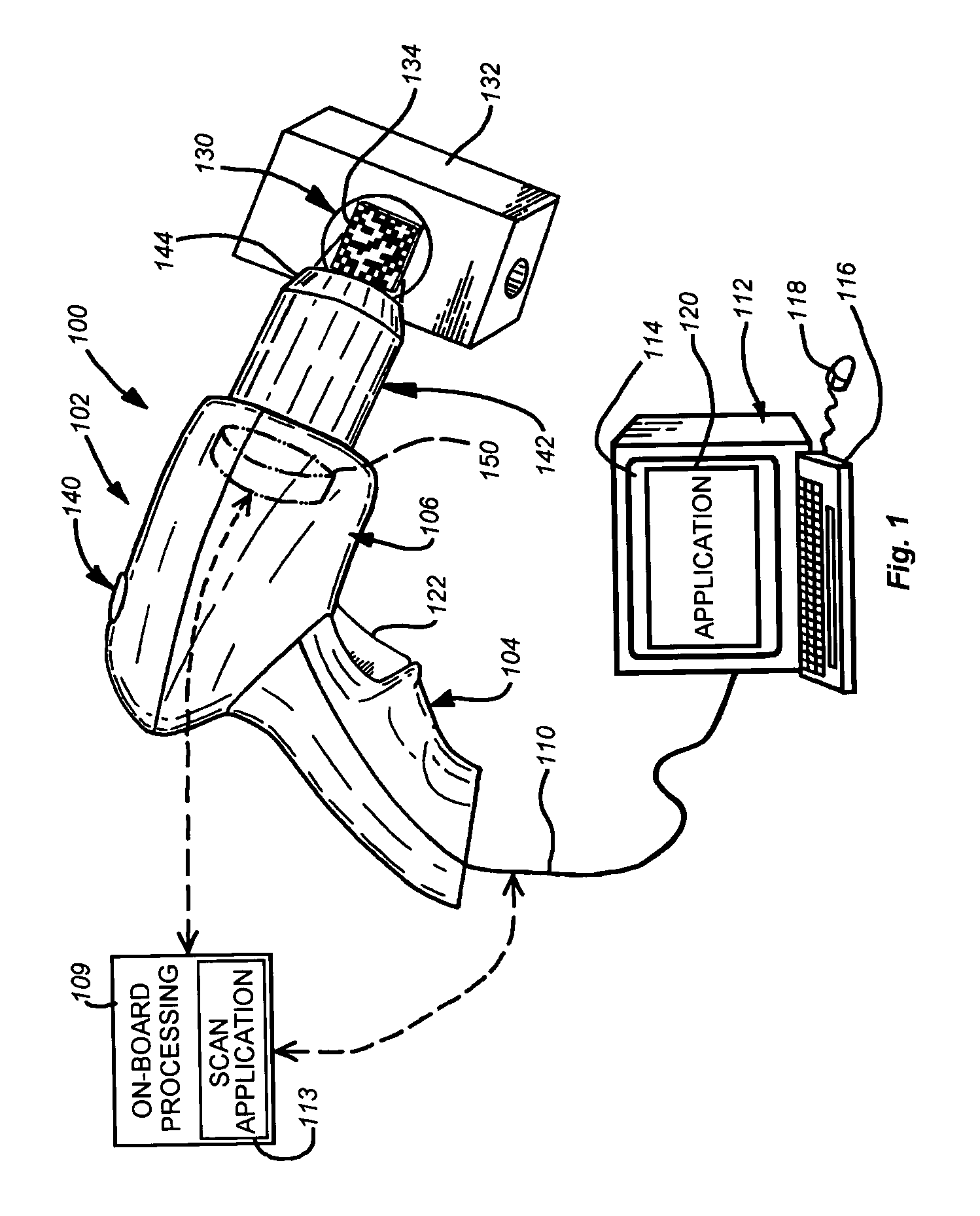
[0023]FIG. 1 shows a scanning system 100 adapted for handheld operation. An exemplary handheld scanning appliance or handpiece 102 is provided. It includes a grip section 104 and a body section 106. The sensor and other functional components described herein can be controlled and can direct image data to an on-board / embedded processor 109. This processor can include a scanning software application 113 by which lighting is controlled, images are acquired and image data is interpreted into usable information (for example, alphanumeric strings derived from the barcode images). The decoded information can be directed via a cable 110 to a PC or other data storage device 112 having (for example) a display 114, keyboard 116 and mouse 118, where it can be stored and further manipulated using an appropriate application 120. Alternatively, the cable 110 can be directly connected to an interface in the scanning appliance and an appropriate interface in the computer 112. In this case the comput...


PUM


Abstract

A system and method is provided for illuminating a subject using a light pipe that transmits light from a source, such as an LED ring illuminator to an outlet that directs the light appropriately as either bright field illumination, dark field illumination or both. The light pipe can include concentric cylinders, typically with a bright field illuminator nested within a dark field illuminator. The tip of the dark field illuminator may be angled so as to internally reflect light inwardly toward the central optical axis of a camera at a low angle. The tip can be located near the focal plane of the camera for the desired field of view. The field of view of the camera sensor can be modified to reject data outside of a illumination field of a particular shape. This illumination field can be created by shaping the light pipe in a predetermined form that projects the modified illumination field. Likewise, a set of aiming illuminators (in, for example, a noticeable color) can be provided around the perimeter of the light pipe to delineate outer boundaries of the illumination field or area of interest. These approaches facilitate better aiming of the sensor into the desired area of interest so that it is illuminated and/or acquired most-fully.

Description

FIELD OF THE INVENTION [0001] This invention relates to illuminators and more particularly to illuminators for image acquisition devices and machine vision systems. BACKGROUND OF THE INVENTION [0002] Machine vision systems use image acquisition devices that include camera sensors to deliver information on a viewed subject. The system then interprets this information according to a variety of algorithms to perform a programmed decision-making and / or identification function. For an image to be most-effectively acquired by a sensor in the visible, and near-visible light range, the subject should be properly illuminated. [0003] In the example of barcode scanning using an image sensor, good lighting is highly desirable. Barcode scanning entails the aiming of an image acquisition sensor (CMOS camera, CCD, etc.) at a location on an object that contains a bar code, and retrieval of an image of that barcode. The bar code contains a set of predetermined patterns that represent an ordered grou...

Claims


Application Information

Patent Timeline
Patent Type & Authority Applications(United States)
IPC IPC(8): G06K7/10
CPCG06K7/10732G06K2207/1011G06K2007/10485G06K7/1404G02B6/0096
Inventor GERST, CARL W. IIIEQUITZ, WILLIAM H.TESTA, JUSTINNADABAR, SATEESH
Owner COGNEX TECH & INVESTMENT
Why Eureka
Try Eureka