Apparatus for an internal combustion engine

a technology for internal combustion engines and actuators, which is applied in the direction of non-mechanical valves, valve drives, machines/engines, etc., can solve the problems of low flow rate through the valve, and the loss of flow to a moderate level

Inactive Publication Date: 2005-04-28
VOLVO LASTVAGNAR AB
View PDF4 Cites 13 Cited by
  • Summary
  • Abstract
  • Description
  • Claims
  • Application Information

AI Technical Summary

Benefits of technology

[0012] To this end, an apparatus configured according to the teachings of the present invention is characterized by the fact that the control members are arranged so

Problems solved by technology

This means that the rate of flow through the valve is always relatively low

Method used


Image

  • Apparatus for an internal combustion engine
  • Apparatus for an internal combustion engine
  • Apparatus for an internal combustion engine

Examples


Embodiment Construction

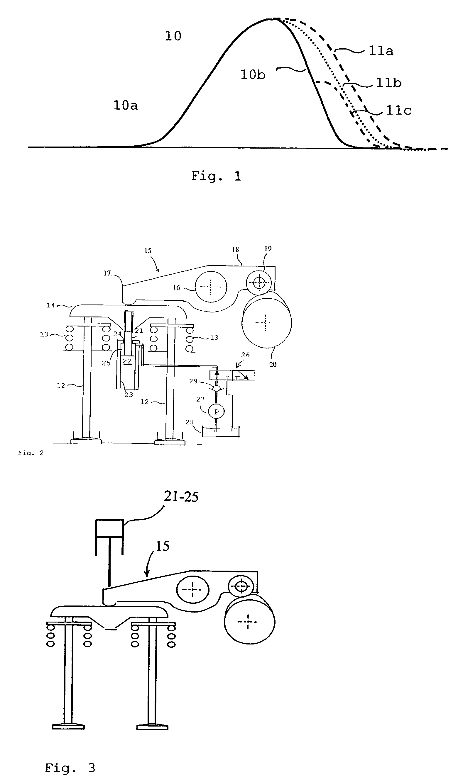
[0017] The graph curve shown in FIG. 1 illustrates how an inlet valve works in an internal combustion engine according to the teachings of the present invention. The engine is designed so that it can switch between a first operating mode corresponding to the solid lines 10 in FIG. 1, and other operating modes corresponding to the lines 11a-11c in FIG. 1. Here, the inlet valve, according to the line 10, follows the rising ramp and falling ramp on a camshaft cam which is designed to operate the internal combustion engine on a Miller cycle with maximum advancement of the inlet valve closure.

[0018] This mode of operation means that the inlet valve closes early enough in the inlet phase to allow the gas volume enclosed in the cylinder to expand before the piston reaches its bottom dead center following the inlet phase. The temperature of the gas volume is thereby reduced, so that subsequent compression and ignition can occur at reduced temperature level, which allows the NOx content of ...


PUM


Abstract

Apparatus and method for controlling valve movements in an internal combustion engine that has at least one inlet valve (12) and at least one exhaust valve for controlling the connection between the combustion chamber in the cylinder and an inlet system and an exhaust system respectively. A rotatable camshaft is provided that has a cam curve including a rising ramp (10a) and a falling ramp (10b) that is designed to interact with a valve mechanism (14) for actuation of the inlet or exhaust valve (12) under the action of a valve spring (13). The valve mechanism (14) includes control members (21, 22, 23, 24, 25 and 26) that allow return movement of the valve mechanism to be controlled during the closing phase of the inlet valve (12) or the exhaust valve, independently of the falling ramp (10b) of the cam curve. The control members (21, 22, 23, 24, 25 and 26) are arranged so that the closing of the valve can be delayed for an adjustable period of time by means of a hydraulically adjustable force counteracting the closing force of the valve spring.

Description

CROSS-REFERENCE TO RELATED APPLICATIONS [0001] The present application is a continuation patent application of International Application No. PCT / SE03 / 01033 filed 18 Jun. 2003 which was published in English pursuant to Article 21(2) of the Patent Cooperation Treaty, and which claims priority to Swedish Application No. 0202124-4 filed 5 Jul. 2002. Said applications are expressly incorporated herein by reference in their entireties. TECHNICAL FIELD [0002] The present invention relates to an apparatus for controlling valve movements in an internal combustion engine which has at least one inlet valve and at least one exhaust valve for controlling the connection between the combustion chamber in the cylinder and an intake system and an exhaust system, respectively. A rotating camshaft is provided that has a cam curve including a rising ramp and a falling ramp that is configured (designed) to interact with a valve mechanism for actuation of the inlet or exhaust valve under the action of a ...

Claims


Application Information

Patent Timeline
IPC IPC(8): F01L1/26F01L9/10F01L13/00F16K31/12
CPCF01L1/08F01L1/181F01L1/267F01L9/02Y02T10/142F01L2013/0089F01L2105/00F02D13/0269F01L13/0015F01L2305/00Y02T10/12F01L9/10
Inventor UDD, SOREN
Owner VOLVO LASTVAGNAR AB
Why Eureka
Try Eureka