

Switching dc-to-dc converter with multiple output voltages
- Summary
- Abstract
- Description
- Claims
- Application Information
AI Technical Summary
Benefits of technology
Problems solved by technology
Method used
Image

Examples
Embodiment Construction
[0045] The preferred embodiments according to the present invention will be described in detail with reference to the drawings.
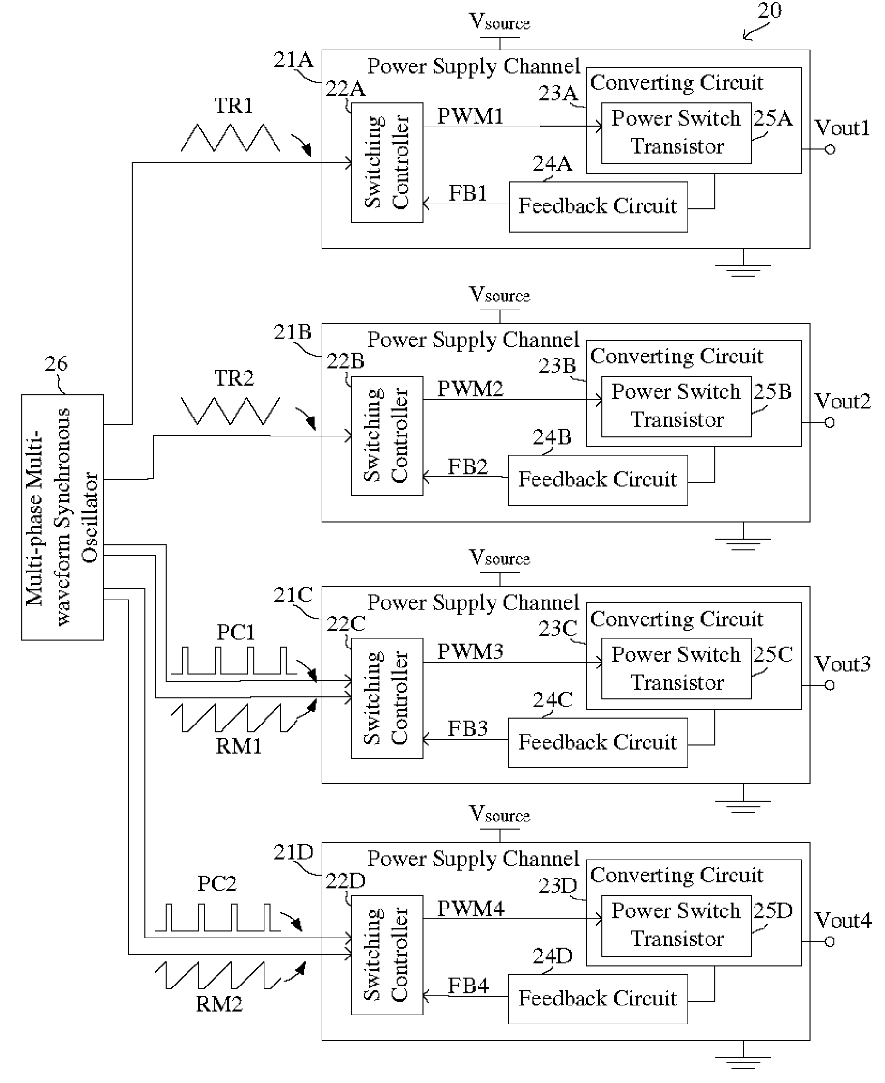
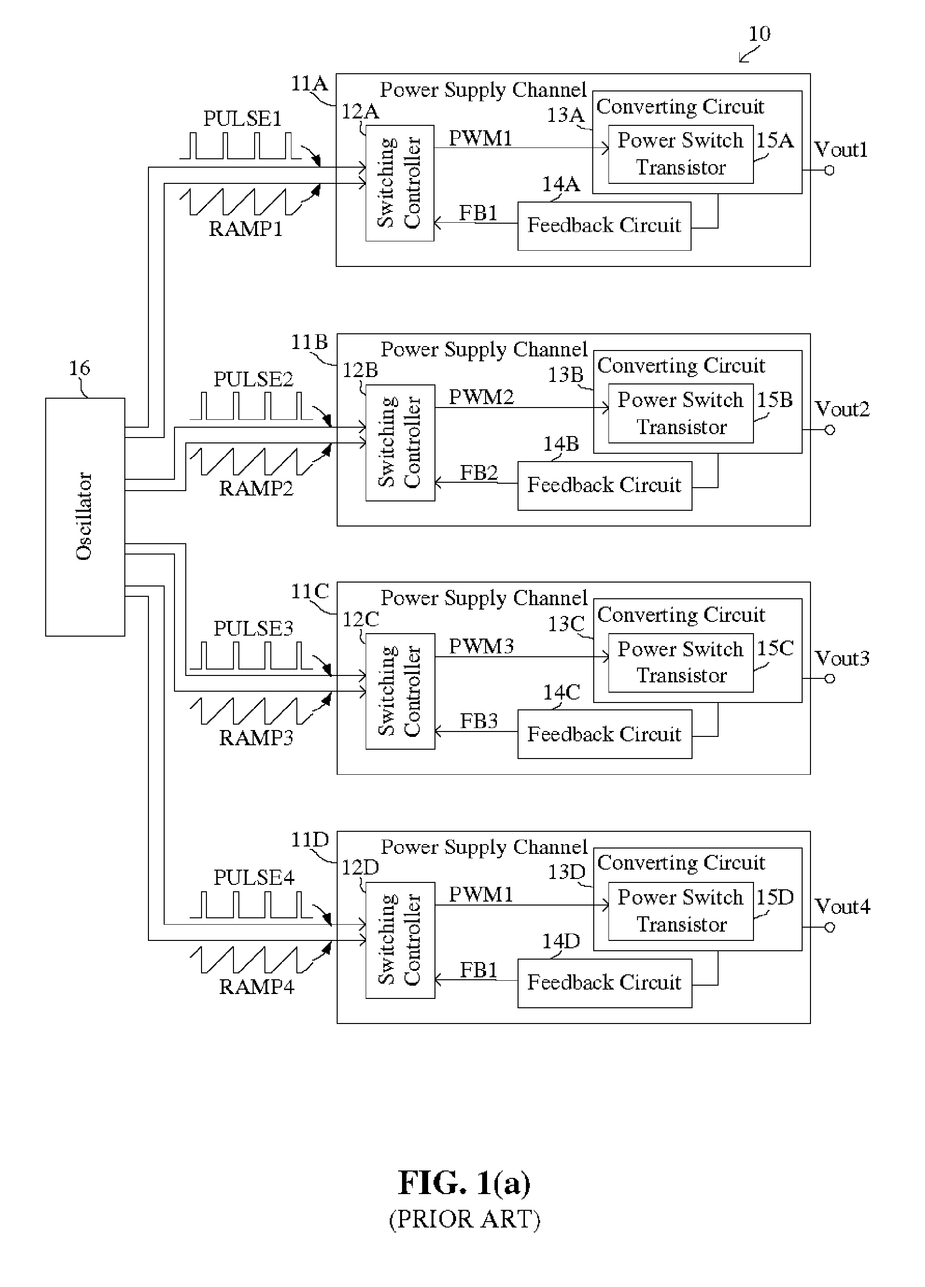
[0046] For clear appreciation of features of the present invention, differences between the present invention and the prior art will be addressed before a detailed description of the preferred embodiments according to the present invention. A switching DC-to-DC converter with multiple output voltages according to the present invention is different from a multiphase or polyphase switching DC-to-DC converter disclosed in, for example, U.S. Pat. No. 5,959,441, U.S. Pat. No. 6,137,274, U.S. Pat. No. 6,144,194, and U.S. Pat. No. 6,246,222. More specifically, the prior art multiphase switching DC-to-DC converter is provided with only one output terminal for supplying a single regulated output voltage; however, the switching DC-to-DC converter according to the present invention is provided with a plurality of output terminals, which are separate from each other, f...
PUM
 Abstract
Description
Claims
Application Information