Projection display

Inactive Publication Date: 2005-04-28
SAMSUNG ELECTRONICS CO LTD
View PDF26 Cites 16 Cited by
  • Summary
  • Abstract
  • Description
  • Claims
  • Application Information

AI Technical Summary

Benefits of technology

[0012] In order sove the above and/or other problems, it is an aspect of the present general inventive concept to provi

Problems solved by technology

However, in such a conventional projection display, a lamp is used as a light source to illuminate optical modulators and has a short life span.
As a result, the additional use of the secondary optics makes an illuminat

Method used


Image

  • Projection display
  • Projection display
  • Projection display

Examples


Example

[0036] Reference will now be made in detail to the embodiments of the present general inventive concept, examples of which are illustrated in the accompanying drawings, wherein like reference numerals refer to the like elements throughout. The embodiments are described below in order to explain the present invention by referring to the figures.

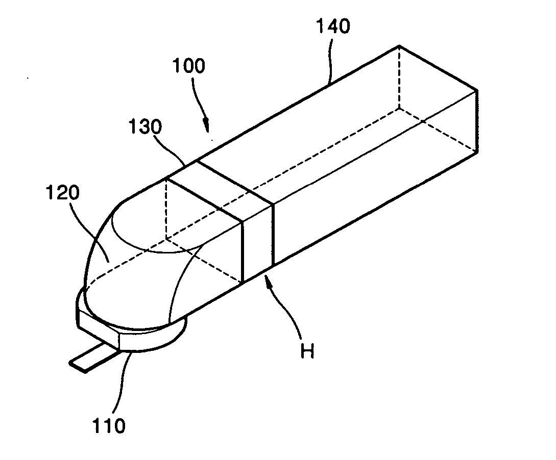
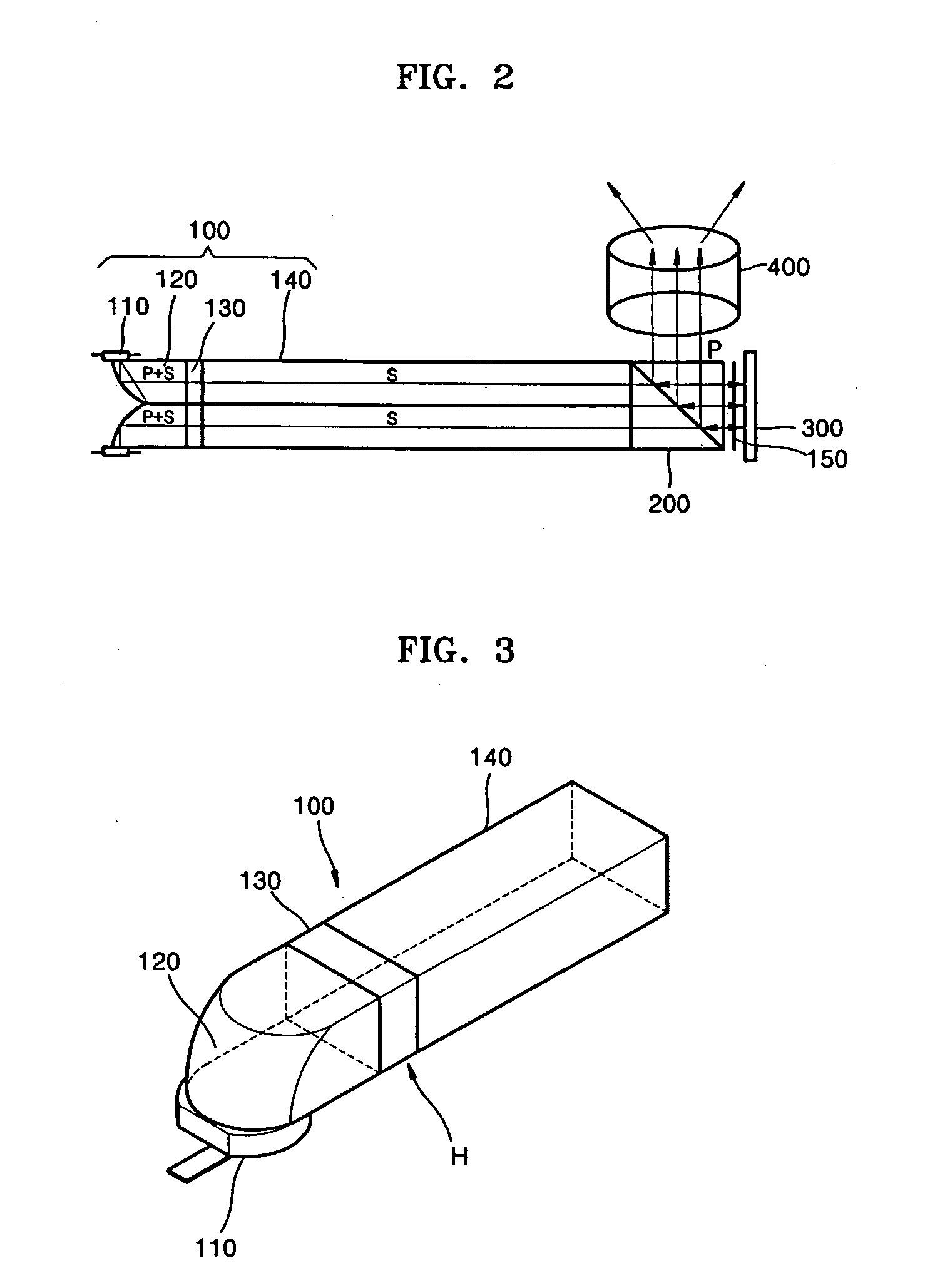
[0037]FIG. 2 is a view showing a structure of a projection display according to an embodiment of the present general inventive concept. Referring to FIG. 2, the projection display may include an illumination unit 100, a polarization beam splitter (PBS) 200, a reflective optical modulator 300, and projection optics 400. The reflective optical modulator 300 can selectively reflect light beams radiating from the illumination unit 100 to modulate the light beams corresponding to image data. The reflective optical modulator 300 may be, for example, a digital micromirror device (DMD), a digital light processor (DLP), a liquid crystal display (LCD) ...


PUM


Abstract

A projection display includes one or more reflective optical modulators and one or more illumination units which illuminate the one or more reflective optical modulators. Each of the one or more illumination units includes at least one collimator which includes a first reflective surface that is parabolic and reflects a light beam radiating from a lower portion toward a side portion, at least one compact light source which is located at a vicinity of a focus of the first reflective surface and sequentially radiates light beams toward the first reflective surface, at least one integrator which transforms light beams to have uniform intensities, and a polarization transformer which is located between the collimator and the integrator and transforms a light beam into one of first and second polarized beams.

Description

CROSS-REFERENCE TO RELATED APPLICATIONS [0001] This application claims the priority of Korean Patent Application No. 2003-75226, filed on Oct. 27, 2003, in the Korean Intellectual Property Office, the disclosure of which is incorporated herein in its entirety by reference. BACKGROUND OF THE INVENTION [0002] 1. Field of the Invention [0003] The present invention relates to a projection display, and more particularly, to a projection display using a compact light source, such as a light emitting diode, as a light source. [0004] 2. Description of the Related Art [0005]FIG. 1 shows the structure of a conventional projection display. Referring to FIG. 1, the conventional projection display includes liquid crystal display (LCD) panels 20 (20R, 20G, and 20B) which are optical modulators, an illumination unit 10 which irradiates light onto the LCD panels 20R, 20G, and 20B, and a projection lens 40 which magnifies and projects a modulated image. [0006] The LCD panels 20R, 20G, and 20B modula...

Claims


Application Information

Patent Timeline
IPC IPC(8): G03B21/00G02B27/18
CPCG03B21/00G03B21/005G02B27/18
Inventor LEE, YOUNG-CHOLMOON, IL-KWEON
Owner SAMSUNG ELECTRONICS CO LTD
Why Eureka
Try Eureka